SIPLACE S-23 HM - 第100页
3 Introduction and Ba sic Concepts User M anual SIPLACE S -23 HM 3.1 Machine Displays and Controls Software Version SR.406.xx 02/00 US Edition 100 3.1.2 Machine Switches and Butt ons The figure below pre sents the pos it…

User Manual SIPLACE S-23 HM 3 Introduction and Basic Concepts
Software Version SR.406.xx 02/00 US Edition 3.1 Machine Displays and Controls
99
3.1.1.1 General
Every station is equipped with a station computer. The station computer, monitor and keyboard
are mounted on a pivoting console above the placement system.
There is an operating panel on both the input and the output side of the placement system. Each
panel has a Start and a Stop button, an emergency stop mushroom-head push-button, a key
switch and a component counter.
NOTE
You can operate the SR software interface either via the keyboard and trackball or via the touch
screen (see section 3.2.1). 3
The position of the switches and buttons (main switch, key-operated switches, start/stop button,
EMERGENCY STOP button etc.) is illustrated in Figure 3.1 - 2. The functions are described in
Chapter 2.
3
WARNING
The machine base doors may only be opened by qualified personnel since certain machine
components carry hazardous voltages.
The relevant accident prevention and applicable regulations (DIN) regarding electrical/electrome-
chanical installations must be strictly complied with. Failure to do so may result in death, severe
physical injury or considerable damage to property. 3
3
3
3
3 Introduction and Basic Concepts User Manual SIPLACE S-23 HM
3.1 Machine Displays and Controls Software Version SR.406.xx 02/00 US Edition
100
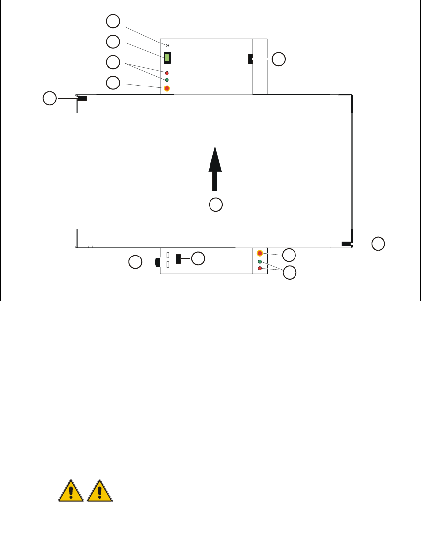
3.1.2 Machine Switches and Buttons
The figure below presents the position of the switches and buttons on the machine. 3
3
Fig. 3.1 - 2 Position of switches and buttons on the machine
Key to Fig. 3.1 - 2
WARNING
Only appropriately qualified personnel are permitted to use the key-operated switch for service or
maintenance work. The key musµµt be removed to prevent unauthorized access as otherwise
serious injury to personnel or damage to the machine may occur. 3
(1) Key-operated switch (2) Component counter
(3) Start and stop buttons (4) Emergency stop mushroom-head push-button
(5) Cover switch, lefthand side (6) Main switch
(7) Cover switch, cover of input conveyor (8) Cover switch, righthand side
(9) Cover switch, cover of output conveyor (10) Direction of PCB transport
1
2
3
4
5
6
7
10
4
3
8
9

User Manual SIPLACE S-23 HM 3 Introduction and Basic Concepts
Software Version SR.406.xx 02/00 US Edition 3.1 Machine Displays and Controls
101
3.1.3 Main Fault Indicator
The main fault indicator (see Figure 3.1 - 1) contains 2 fault indicator lights (white) together with
an operating indicator light (green) 3
The operating indicator light is located between the two fault indicator lights. This indicates
whether the machine is in production or wait mode. 3
The nature and location of any malfunction can be identified using the operating indicator light
(flashing, glowing etc.) and the two fault indicator lights. 3
The following section describes the information provided by the two fault indicator lights. 3
3.1.3.1 Functions
General Operating Statuses: 3
– Operating indicator light continuously illuminated
The machine is operating.
– Operating indicator light flashes
The machine is waiting for a PCB in the input conveyor or is waiting for the output conveyor to
become free.
– Fault light flashes
One or more tracks are empty at the feeder location of the gantry in question.
However, the machine will process any components present.
– Fault light continuously illuminated
An error has occured at the gantry in question--> the machine has stopped.
– Both lights continuously illuminated
An error has occurred which affects the entire machine--> the machine has stopped.
3.1.4 Barcode Reader
The barcode reader is available as an option. It is very helpful, particularly under production
conditions, since component barcodes on component reels and track barcodes can be read in
quickly and reliably from the barcode strip on the machine.
An acoustic signal sounds each time a data record is successfully read in.
NOTE
For a detailed description of the function, connection and operation of the bar code reader, refer
to chapter 11 Station extensions / hardware. 3