SIPLACE S-23 HM - 第101页
User Manual SIPLACE S-23 HM 3 Introduction and Basic Concepts Software Version SR.406.xx 02/00 US Edition 3.1 Machine Displays and Controls 101 3.1.3 Main Fault Indicator The main fa ult ind icator (s ee Figure 3.1 - 1) …
3 Introduction and Basic Concepts User Manual SIPLACE S-23 HM
3.1 Machine Displays and Controls Software Version SR.406.xx 02/00 US Edition
100
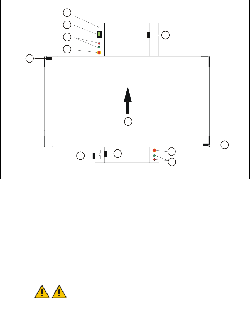
3.1.2 Machine Switches and Buttons
The figure below presents the position of the switches and buttons on the machine. 3
3
Fig. 3.1 - 2 Position of switches and buttons on the machine
Key to Fig. 3.1 - 2
WARNING
Only appropriately qualified personnel are permitted to use the key-operated switch for service or
maintenance work. The key musµµt be removed to prevent unauthorized access as otherwise
serious injury to personnel or damage to the machine may occur. 3
(1) Key-operated switch (2) Component counter
(3) Start and stop buttons (4) Emergency stop mushroom-head push-button
(5) Cover switch, lefthand side (6) Main switch
(7) Cover switch, cover of input conveyor (8) Cover switch, righthand side
(9) Cover switch, cover of output conveyor (10) Direction of PCB transport
1
2
3
4
5
6
7
10
4
3
8
9

User Manual SIPLACE S-23 HM 3 Introduction and Basic Concepts
Software Version SR.406.xx 02/00 US Edition 3.1 Machine Displays and Controls
101
3.1.3 Main Fault Indicator
The main fault indicator (see Figure 3.1 - 1) contains 2 fault indicator lights (white) together with
an operating indicator light (green) 3
The operating indicator light is located between the two fault indicator lights. This indicates
whether the machine is in production or wait mode. 3
The nature and location of any malfunction can be identified using the operating indicator light
(flashing, glowing etc.) and the two fault indicator lights. 3
The following section describes the information provided by the two fault indicator lights. 3
3.1.3.1 Functions
General Operating Statuses: 3
– Operating indicator light continuously illuminated
The machine is operating.
– Operating indicator light flashes
The machine is waiting for a PCB in the input conveyor or is waiting for the output conveyor to
become free.
– Fault light flashes
One or more tracks are empty at the feeder location of the gantry in question.
However, the machine will process any components present.
– Fault light continuously illuminated
An error has occured at the gantry in question--> the machine has stopped.
– Both lights continuously illuminated
An error has occurred which affects the entire machine--> the machine has stopped.
3.1.4 Barcode Reader
The barcode reader is available as an option. It is very helpful, particularly under production
conditions, since component barcodes on component reels and track barcodes can be read in
quickly and reliably from the barcode strip on the machine.
An acoustic signal sounds each time a data record is successfully read in.
NOTE
For a detailed description of the function, connection and operation of the bar code reader, refer
to chapter 11 Station extensions / hardware. 3

3 Introduction and Basic Concepts User Manual SIPLACE S-23 HM
3.1 Machine Displays and Controls Software Version SR.406.xx 02/00 US Edition
102
3.1.5 Station Computer
The station computer is a desktop model and is equipped with a 3
1
/
2
" floppy drive and a CD-ROM
drive. The operating system is Microsoft Windows NT 4.0 and the graphical user interface for the
placement system is based on the Windows standard. 3
3.1.6 Monitor
The color monitor with integrated touch screen acts as the display and operating tool for the
graphic user interface of the SC software. You select functions using your finger which guides the
mouse pointer over the screen itself. 3
Actions can be executed by touching the corresponding object (e.g. button or icon) on the
screen. 3
CAUTION
Protect the monitor from humidity and excessive heat (sunlight, room heating).
Never obstruct the ventilation slots.
Never try to remove the cover.
Make sure that no moisture is able to penetrate the inside of the monitor.
Make sure that the operating voltage is set correctly.
Make sure that the brightness and contrast of the screen display are set to medium values since
these greatly prolong the lifetime of the screen. 3
3
NOTE
Each monitor is supplied with a separate User Manual and you should follow the warnings and
safety instructions it contains.
Please refer to the Manual for a description of the connections and setting options. By default, the
resolution of the screen display is set to 640 x 480 pixels. 3
3
3