SIPLACE S-23 HM - 第107页
User Manual SIPLACE S-23 HM 3 Introduction and Basic Concepts Software Version SR.406.xx 02/00 US Edition 3.2 Principles of the Graphic User I nterface 107 3.2.2.1 Icons in the W orking or Display Area In main v iew , ce…
3 Introduction and Basic Concepts User Manual SIPLACE S-23 HM
3.2 Principles of the Graphic User Interface Software Version SR.406.xx 02/00 US Edition
106
Caption bar 3
The caption bar displays the name of the current view (e.g. main view). 3
Menu bar 3
The menu bar contains menus, the contents of which (functions and options available in the menu)
may change depending on the current view. 3
Working area/display area 3
This area displays the controls (buttons, icons) used to set/activate functions, the contents of
active menus and submenus, general messages, error messages and other comments. In
addition, in the main view, animated and/or different color objects are used to indicate certain
processes or statuses (e.g. processing, feeder location empty etc.). 3
Controls 3
You trigger actions, select options or make settings by clicking the corresponding controls with the
left mouse button.
If a control is displayed in inverse video (light gray), this means that the conditions for the
execution of the corresponding functions are not satisfied. 3
Status area 3
The status area displays the current machine status, the last error to have occurred and the action
which is to be performed by the operator
If the "GEM Interface" option has been configured, the status of the connection to the host
computer is also displayed at the right-hand side of the area. 3
Toolbar 3
This bar contains buttons which you use to switch the user interface to a different view where you
can perform the necessary operations. When you click a toolbar button, the user interface
switches to the view which corresponds to it. The button matching the active view then itself
becomes inactive. 3
Info bar 3
This bar displays concise information about the menu item or icon/button over which the mouse
pointer is currently positioned. The current control mode is displayed next to this in a separate
area. 3
User Manual SIPLACE S-23 HM 3 Introduction and Basic Concepts
Software Version SR.406.xx 02/00 US Edition 3.2 Principles of the Graphic User Interface
107
3.2.2.1 Icons in the Working or Display Area
In main view, certain operating statuses (processing, error etc.) are indicated by different icons or
by changes in the color of the corresponding graphic in the display area. 3
Meaning of the individual operating status icons 3
3
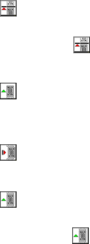
Pause processing 3
You can pause the processing in order to carry out single functions, for example. 3
Å Click on the icon.
Processing will be paused as soon as the PCB on the center conveyor is complete. The color
of the "Processing" icon will change to green.
3
Process 3
If you paused processing (placement) of a PCB in order to switch to the "Single functions" menu,
for example, you can click on this icon to resume placement. The color of the "Pause processing"
icon will change to red. 3
3
Cancel processing 3
The color of the icon changes to red. Click on this icon to cancel processing a PCB (after a fatal
error message, for example). You will be prompted to confirm this action.
3
Continue processing 3
The color of the icon changes to green. 3
3
Å Click on the icon if you wish to continue processing the PCB even after a fatal error mes-
sage, for example. The placement process will be resumed.
3

3 Introduction and Basic Concepts User Manual SIPLACE S-23 HM
3.2 Principles of the Graphic User Interface Software Version SR.406.xx 02/00 US Edition
108
Meaning of the other icons and markings 3
A message window will be overlaid if a track, machine or transport error occurs (see the following
examples). 3
Machine error gantry 1 3
3
3
3
3
3
3
3
3
Track empty error 3
3
3