SIPLACE S-23 HM - 第184页
6 Vision functions User M anual SIPLACE S -23 HM 6.1 The vision systems on the placement system Software Version SR.406.xx 02/00 US E dition 184 6 Fig. 6.1 - 4 Vision analysis unit
User Manual SIPLACE S-23 HM 6 Vision functions
Software Version SR.406.xx 02/00 US Edition 6.1 The vision systems on the placement system
183
The PCB camera system (see items 1 and 2 in Fig. 6.1 - 3) essentially consists of the following
components: 6
– Lens system
– CCD chip
– CCD camera amplifier
– An illumination plane for illuminating PCB fiducials and ink spots
The PCB camera system is fixed to the revolver head mount on the underside of the gantry. As
standard, it can center PCBs from 50 mm x 50 mm up to 460 mm x 460 mm (2" x 2" to 18" x 18")
in size, with the thickness ranging from 0.5 mm to 4.5 mm. 6
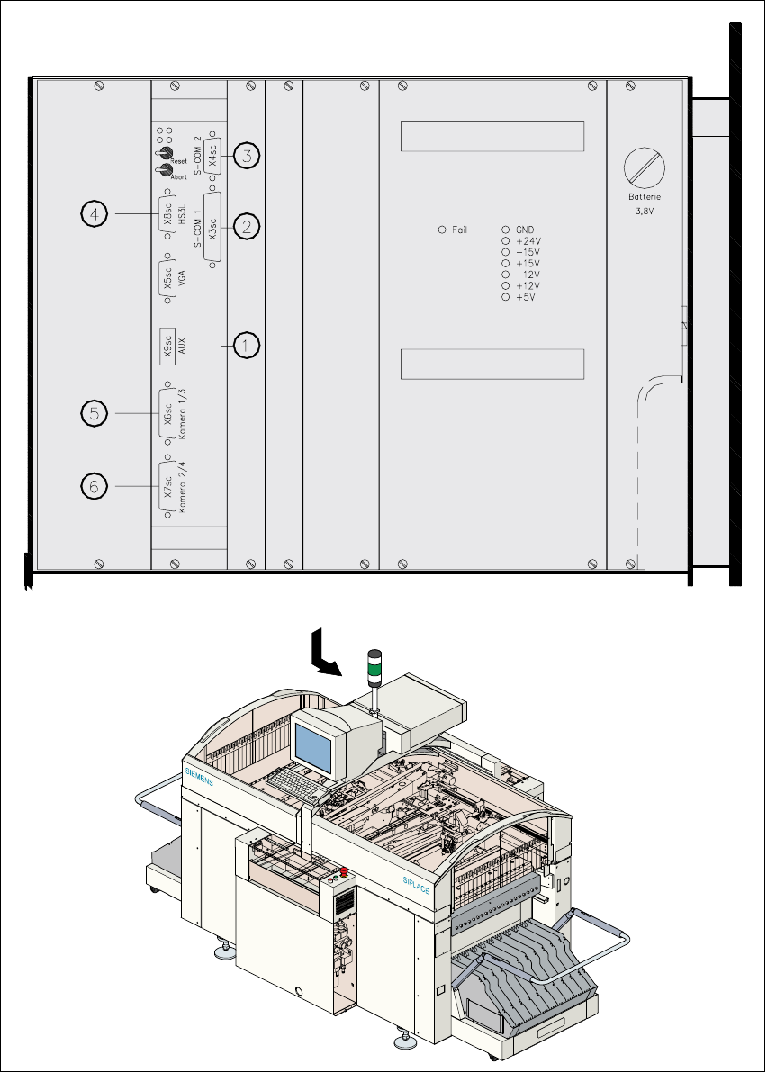
6.1.3 Vision analysis unit
The vision analysis unit (see item 1 in Fig. 6.1 - 4) is plugged into the placement system’s control
unit. 6
It processes and analyzes electrical signals from the component and PCB camera systems. Cor-
rection values are calculated from any deviations from setpoint. These values are then used for
recalculating the placement positions and angle of rotation for placement. 6
The vision analysis unit also performs a component identification process. The precise component
pick-up position, which is particularly important for small components, is also determined in the
vision analysis unit. 6
6 Vision functions User Manual SIPLACE S-23 HM
6.1 The vision systems on the placement system Software Version SR.406.xx 02/00 US Edition
184
6
Fig. 6.1 - 4 Vision analysis unit
User Manual SIPLACE S-23 HM 6 Vision functions
Software Version SR.406.xx 02/00 US Edition 6.1 The vision systems on the placement system
185
Key to Fig. 6.1 - 4
(1) MVS 340 vision analysis unit
(2) COM1 interface
(3) COM2 interface
(4) HS
3
L interface
(5) Camera connections:
1 PCB camera, gantry 1
3 Component camera, gantry 1
(6) Camera connections:
2 PCB camera, gantry 2
4 Component camera, gantry 2
6
The electronic image signals from components, PCB fiducials and feeder module fiducials can be
transferred from the vision analysis unit via the video multiplexer to the station monitor, where they
are used for measuring and testing purposes. 6