SIPLACE S-23 HM - 第24页
1 Introduction, technical data User M anual SIPLACE S -23 HM 1.4 Revision index Software Vers ion SR.406.xx 02/00 US Edition 24 1.4 Rev ision index 1 1.4.1 Overvie w of the revi sions in the 0 2/00 edition 1 Manual Softw…

User Manual SIPLACE S-23 HM 1 Introduction, technical data
Software Version SR.406.xx 02/00 US Edition 1.3 User classification
23
Line engineers 1
Line engineers have undergone special training and are authorized to carry out line engineer ac-
tivities, such as creating set-up configurations, determining vision parameters, etc. 1
Service engineers 1
This class is reserved for Siemens engineers, who are trained to carry out servicing work and to
upgrade and retrofit the placement system. 1
WARNING
A thorough knowledge of the relevant part of this User Manual is re-
quired before carrying out any work on the machine. All work must be carried out by appropriately
trained and qualified personnel. All warning, caution and danger notes MUST be observed. 1
PLEASE NOTE: The content of this User Manual is not part of or intended to modify a previous
or existing agreement, undertaking or legal relationship. Any undertakings entered into by Sie-
mens AG result from the purchase contract, which also contains complete and generally applica-
ble guarantees. Such contractual guarantee provisions are neither extended nor restricted by the
information given in this User Manual. 1

1 Introduction, technical data User Manual SIPLACE S-23 HM
1.4 Revision index Software Version SR.406.xx 02/00 US Edition
24
1.4 Revision index
1
1.4.1 Overview of the revisions in the 02/00 edition
1
Manual Software version Issue
First draft S-23 HM Provisional User Manual 405 01/99
Revision S-23 HM User Manual 405 05/99
Revision S-23 HM User Manual 406 02/00
New or modified Chapter/Section
6,3/$&(RQWKH:RUOG:LGH:HE::: 1.1.1
Safety instructions for the PCB barcode reader (option) 2.1.7
Safety instructions for coupling and uncoupling the mobile
changeover table
2.1.8
Safety instructions for changing the height of component tables 2.1.9
Safety instructions for the changeable component feeder table 2.1.10
"Mode" Menu 3.3.2.1
"Language" Menu 3.3.2.4
What should you do ... 7
Copying a help file 9.1.2.1
3 x 8 mm S module 10.2.2
3 x 8 mm S module for 0201/0402 components 10.2.3
PCB barcode 11.4
Ceramic substrate centering 11.5
Fine calibration 11.8
User Manual SIPLACE S-23 HM 1 Introduction, technical data
Software Version SR.406.xx 02/00 US Edition 1.5 Description of the machine
25
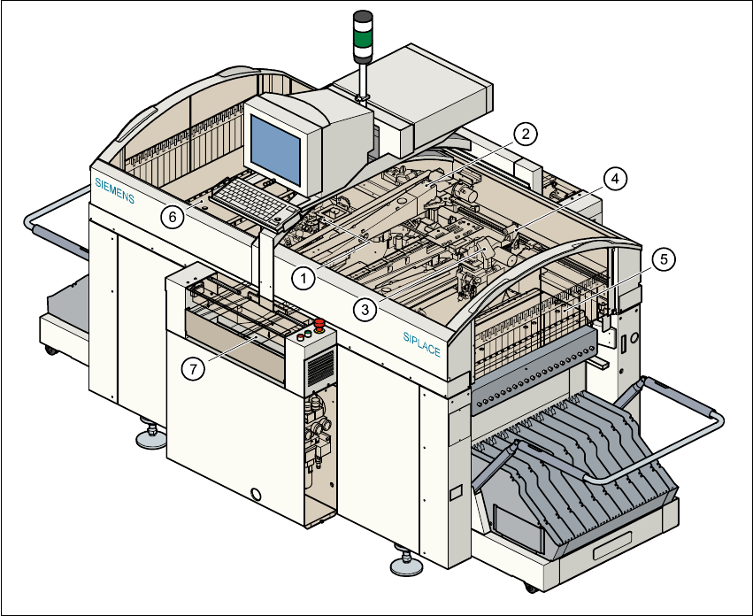
1.5 Description of the machine
1.5.1 Functional description
The automatic placement system is a high-performance placement system with two gantrY-axis
systems. A PCB vision system and a star-shaped 12-segment revolver head are mounted on each
gantry. Revolver placement heads equipped with a component vision system pick up the compo-
nents from stationary feeder modules and place them onto the PCB clamped in the PCB con-
veyor. 1
1
Fig. 1.5 - 1 Functional description of the placement system
(1) 12-segment revolver head /DLM1 with component vision module (gantry 1)
(2) Gantry 1 with PCB vision module
(3) 12-segment revolver head /DLM1 with component vision module (gantry 2)
(4) Gantry 2 with PCB vision module
(5) Stationary component supply (location 1)
(6) Stationary component supply (location 3)
(7) PCB conveyor (dual conveyor option)