SIPLACE S-23 HM - 第25页
User Manual SIPLAC E S-23 HM 1 Introduction, technical dat a Software Vers ion SR.406.xx 02/00 US Edition 1.5 Description of the machine 25 1.5 Description of the machine 1.5.1 Functional description The automati c place…

1 Introduction, technical data User Manual SIPLACE S-23 HM
1.4 Revision index Software Version SR.406.xx 02/00 US Edition
24
1.4 Revision index
1
1.4.1 Overview of the revisions in the 02/00 edition
1
Manual Software version Issue
First draft S-23 HM Provisional User Manual 405 01/99
Revision S-23 HM User Manual 405 05/99
Revision S-23 HM User Manual 406 02/00
New or modified Chapter/Section
6,3/$&(RQWKH:RUOG:LGH:HE::: 1.1.1
Safety instructions for the PCB barcode reader (option) 2.1.7
Safety instructions for coupling and uncoupling the mobile
changeover table
2.1.8
Safety instructions for changing the height of component tables 2.1.9
Safety instructions for the changeable component feeder table 2.1.10
"Mode" Menu 3.3.2.1
"Language" Menu 3.3.2.4
What should you do ... 7
Copying a help file 9.1.2.1
3 x 8 mm S module 10.2.2
3 x 8 mm S module for 0201/0402 components 10.2.3
PCB barcode 11.4
Ceramic substrate centering 11.5
Fine calibration 11.8
User Manual SIPLACE S-23 HM 1 Introduction, technical data
Software Version SR.406.xx 02/00 US Edition 1.5 Description of the machine
25
1.5 Description of the machine
1.5.1 Functional description
The automatic placement system is a high-performance placement system with two gantrY-axis
systems. A PCB vision system and a star-shaped 12-segment revolver head are mounted on each
gantry. Revolver placement heads equipped with a component vision system pick up the compo-
nents from stationary feeder modules and place them onto the PCB clamped in the PCB con-
veyor. 1
1
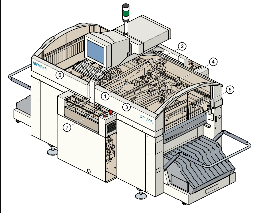
Fig. 1.5 - 1 Functional description of the placement system
(1) 12-segment revolver head /DLM1 with component vision module (gantry 1)
(2) Gantry 1 with PCB vision module
(3) 12-segment revolver head /DLM1 with component vision module (gantry 2)
(4) Gantry 2 with PCB vision module
(5) Stationary component supply (location 1)
(6) Stationary component supply (location 3)
(7) PCB conveyor (dual conveyor option)

1 Introduction, technical data User Manual SIPLACE S-23 HM
1.5 Description of the machine Software Version SR.406.xx 02/00 US Edition
26
The concept behind the automatic placement system 1
– with its stationary feeder modules,
– PCBs that do not move during placement
– and positionable placement heads
has a number of significant benefits: 1
– For example, the flexible 12-segment revolver heads combined with automatic nozzle chang-
ers enable the nozzle configuration to be changed temporarily and automatically adapted to
receive different component sizes. You can also optimize the traversing paths and the place-
ment sequence.
– With stationary feeder modules, even the tiniest components are picked up reliably.
– The components cannot slip on the PCB during placement (as is often the case with moving
PCBs) since the PCB does not move.
– Sophisticated optical centering systems (vision systems) for components and PCBs also en-
sure high component positioning accuracy.
– Components can be topped up and tapes can be spliced without stopping the machine.
– Prepared component tables enable the placement system to be retooled without long stop-
pages.
1.5.2 Head Modularity concept (HM)
The abbreviation HM in the designation of the SIPLACE S-23 HM placement system stands for
Head Modularity. 1
The aim of this concept is to allow any combination of 6-nozzle and 12-nozzle revolver heads to
be used on the placement system. A simple head change procedure will enable the system to be
quickly adapted to the requirements of individual placement jobs. 1
The head modularity concept will be implemented in the next development stage. Placement sys-
tems supplied with the designation HM are designed to be compatible with the new concept. 1