SIPLACE S-23 HM - 第294页
6 Vision functions User M anual SIPLACE S -23 HM 6.6 Test Component Software Version SR.406.xx 02/00 US Edition 294 Measu ring times can be reduced by lower ing the reso lution in the measurin g or integrati on direc- ti…
User Manual SIPLACE S-23 HM 6 Vision functions
Software Version SR.406.xx 02/00 US Edition 6.6 Test Component
293
Use package form edges 6
–
for rotation windows
The package form edges can be used to optimally position the rotation windows. However, to
do this, the package form edge must be visible and it must not contain a row of leads (eg white
plugs).
–
for translation windows
The package form edges can be used to optimally position the translation windows. However,
to do this, the package form edge must be visible and it must not contain a row of leads.
PLEASE NOTE:
Do not use measurement mode Row together with measurement mode Size. 6
Integration settings 6
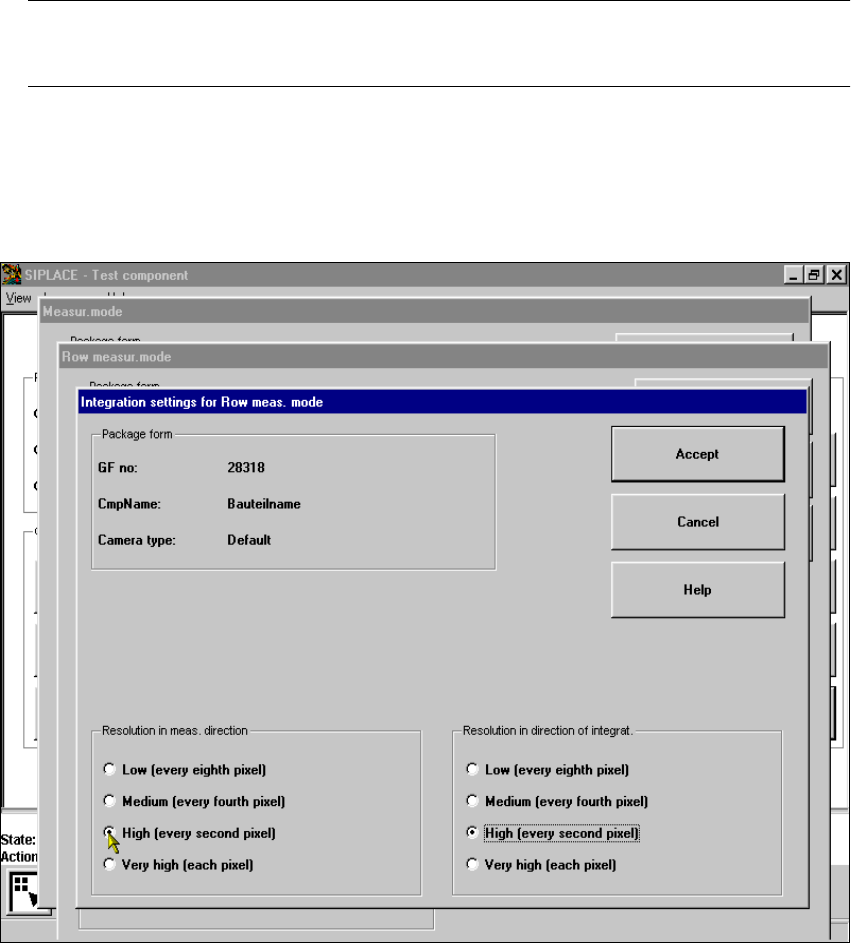
Once you have clicked on the ‘Integration settings’ field, the Row measuring mode integration
settings menu will appear on screen. 6
6
Fig. 6.6 - 38 Measuring mode option, Row measuring mode integration settings menu
6 Vision functions User Manual SIPLACE S-23 HM
6.6 Test Component Software Version SR.406.xx 02/00 US Edition
294
Measuring times can be reduced by lowering the resolution in the measuring or integration direc-
tion. However, you must ensure that the structure to be analyzed has a sufficient number of pixels.
Otherwise, the measuring quality will be compromised. We recommend to choose a very high or
high resolution. 6
6.6.4.18 ‘Corner’ measuring mode
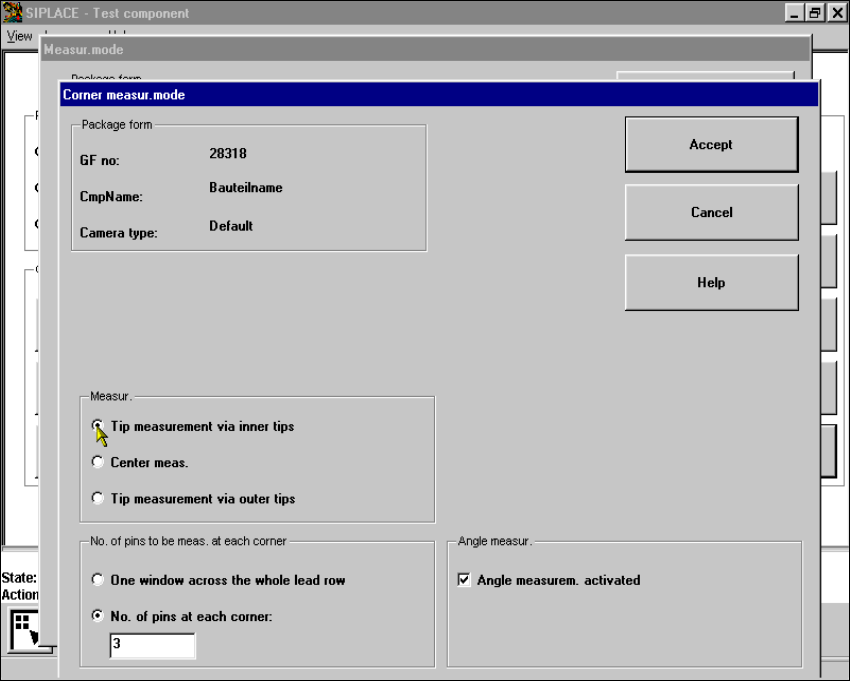
Click on the ‘Setting’ field in the ‘Corner’ measuring mode to call up the Corner measuring mode
menu. 6
6
Fig. 6.6 - 39 Measuring mode option, Corner measuring mode menu
This menu is used to 6
– specify the lead measuring method.
– select the number of leads to be measured at each corner.
– switch the angle measurement on or off.

User Manual SIPLACE S-23 HM 6 Vision functions
Software Version SR.406.xx 02/00 US Edition 6.6 Test Component
295
Measurement 6
If the inner lead tips are mapped better than the outer tips, for example, if a shiny lead is bent up-
wards slightly, you can select one of the following options: 6
– measuring the tips via the inner tips of the leads, for bases, for example
– center of the lead, center measurement, for PLCC, SOI, for example
– measuring the tips via the outer tips of the leads, for QFP, SOT, SO, for example
Number of leads to be measured at each corner 6
If the lead does no longer stand out well from the background, in the case of white plugs, for ex-
ample, use this option to specify the number of leads to be measured. However, to do this, the
component must be fully described in the line computer (FDC). 6
NOTE 6
This value should only be modified for special components and plugs. Deactivate lead measure-
ment for white plugs. 6
Angle measurement 6
For single-row components, the angle of rotation is not calculated correctly. Consequently it is bet-
ter to access calculation of the angle of rotation in Row measuring mode. Switch off the angle
measurement in this option. 6