SIPLACE S-23 HM - 第339页
User Manual SIPLAC E S-23 HM 7 What s hould you do ... Software Version SR.406.xx 02/00 US Edition 7.9 How to avoid track errors 339 7.9 How to avoid track errors 7.9.1 General informat ion Å Make sure tha t the area s a…

7 What should you do ... User Manual SIPLACE S-23 HM
7.8 Component table, mobile Software Version SR.406.xx 02/00 US Edition
338
7.8.3 Docking the component table
WARNING 7
Check that the placement head is outside the range of the component table. 7
CAUTION 7
When docking the component table, ensure that the table bed is in its top end position and the
bracket (item 7) is folded up. 7
Å Cut off the empty tapes for the feeder modules.
Å Make sure that the contact surface (item 10) for the component table bed is clean.
Å CAREFULLY push the component table into the placement system.
Å Connect the compressed air supply (item 3).
Å Plug in the control cable (item 1).
Å Plug in the power cable (item 2) for the component table.
Å Pull the two actuating tubes (item 6) towards you at the same time and then lower the bracket
(item 7) in order to be able to lower the component table bed.
Å Check that the centring holes in the component table bed lie precisely over the centering pins
of the placement system.
Å Hold down the button (item 5) until the component table bed reaches its top end position.
Å Release the button and the component table bed will descend.
Å Ensure that the centring pins engage in the centring holes in the component table bed and that
the component table bed is fully lowered.
Å Fold up the bracket (item 7) of the component table.
Å Lock the two horizontal tensioners (item 11).
Å Close the side screens and protective cover.
Å Press the Start button to start the placement system.
User Manual SIPLACE S-23 HM 7 What should you do ...
Software Version SR.406.xx 02/00 US Edition 7.9 How to avoid track errors
339
7.9 How to avoid track errors
7.9.1 General information
Å Make sure that the areas around the feeder modules are clean and that there are no loose
components in the feeder area or under the feeder modules.
Å Ensure that the supporting surfaces of the feeder modules, and particularly the magnetic rails
of the component tables, are clean and level.
Å Refill promptly with components.
Å Splice the tapes promptly. This generally means that you are to prepare the splicing material
when there is still approximately 1.5 m of tape on the reel.
Å Handle the feeder modules carefully when you insert them into or remove them from the com-
ponent table as these are high-precision devices.
Å When you insert the feeder modules, make sure that you do not accidentally press one of the
program keys. If you do, you could change the advance from 4 mm to 2 mm on
8 mm S feeder modules, for example.
Å Close the flaps of the feeder modules because they can be easily damaged when open.
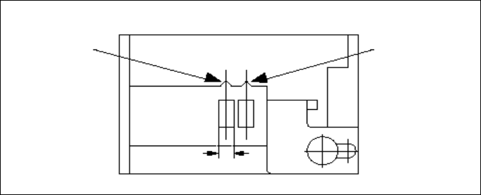
Å For 8 mm S feeder modules, make sure that the components are picked up from the correct
position, depending on their sizes (see the following example).
Example for 8mm S feeder modules 7
7
Å Check to see if all the plugs of the feeder modules are plugged in to the correct sockets.
Pick-up position
Pick-up position
> 3 mm
for components
≤ 3 mm
for components
Width
7 What should you do ... User Manual SIPLACE S-23 HM
7.9 How to avoid track errors Software Version SR.406.xx 02/00 US Edition
340
7.9.2 ... on the 8 mm S tape feeder module
Å NEVER open the cover flap without first releasing the tension of the cover foil remover.
Å Set the pick-up position and the spacing of the tape according to the short instructions en-
closed with each tape feeder module.
Å Insert the tape material over the spring into the tape feeder module.
7.9.3 ... on the tape container
Å Insert the spacers correctly (see Fig. 7.5 - 2).
Å Use insertable shafts for large tape reels.