SIPLACE S-23 HM - 第34页
1 Introduction, technical data User M anual SIPLACE S -23 HM 1.10 Setting up the placement system Software Version SR.406.xx 02/00 US Edition 34 1.10 Setting up the plac ement system 1.10.1 T ransport dimensions 1 Fig. 1…
User Manual SIPLACE S-23 HM 1 Introduction, technical data
Software Version SR.406.xx 02/00 US Edition 1.9 Dimensions and weight of the placement system
33
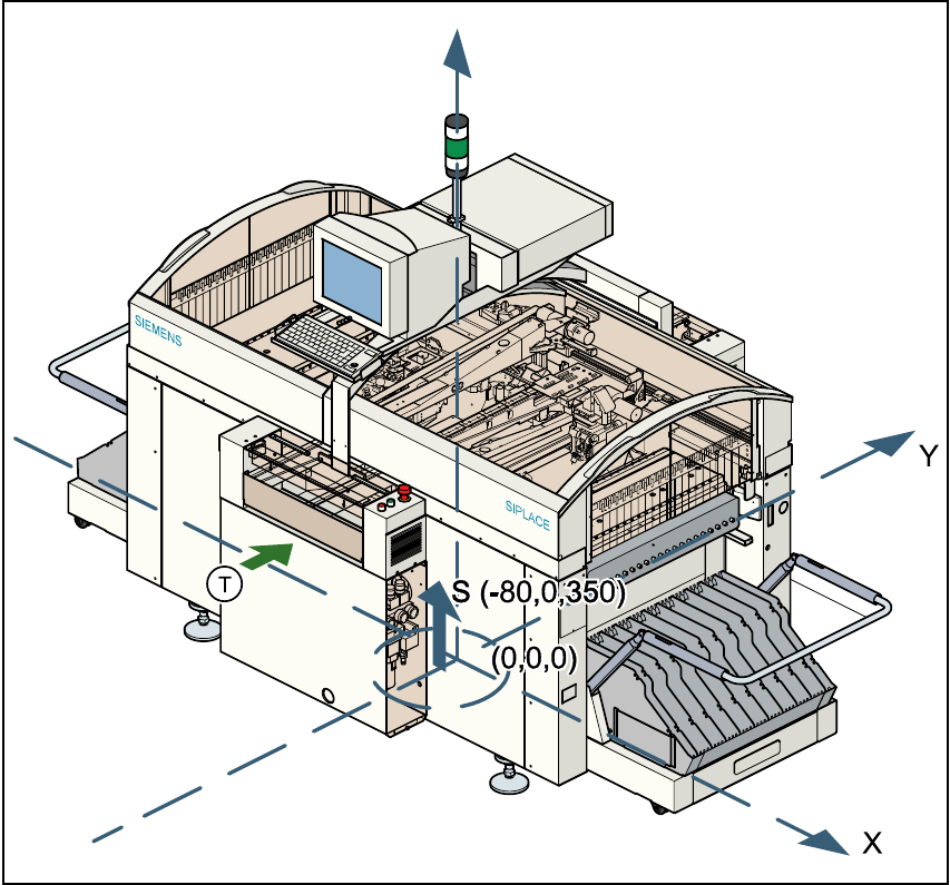
1.9.3 The placement system’s center of gravity
1
Fig. 1.9 - 2 The placement system’s center of gravity
X coordinate -80 mm 1
Y coordinate 0 mm 1
Z coordinate 350 mm high 1
T PCB transport direction 1
1
These center of gravity coordinates relate to placement systems with a PCB transport height of
830 mm. 1
1 Introduction, technical data User Manual SIPLACE S-23 HM
1.10 Setting up the placement system Software Version SR.406.xx 02/00 US Edition
34
1.10 Setting up the placement system
1.10.1 Transport dimensions
1
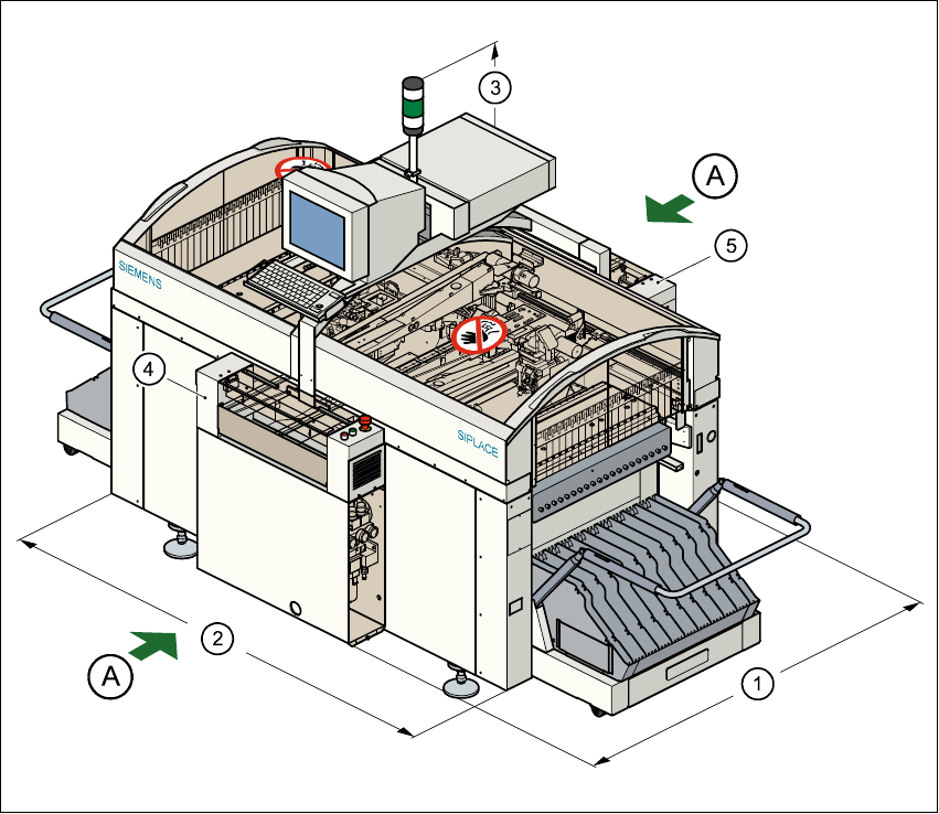
Fig. 1.10 - 1 Dimensions of the placement system during transportation and setting up
A Points for attaching the fork-lift truck (fork length 1600 mm) 1
(1) Length 1587 mm
(2) Width 1921 mm
(3) Height 1836 mm
(4) Input conveyor
(5) Output conveyor
1
The PCB conveyor height is 830 mm ± 15 mm. 1
User Manual SIPLACE S-23 HM 1 Introduction, technical data
Software Version SR.406.xx 02/00 US Edition 1.10 Setting up the placement system
35
1.10.2 Transport configuration and transportation
The following components are not installed when the placement system is delivered from the fac-
tory: 1
– keyboards
–monitors
– fault indicator lamps and
– component tables
Å Install the dismantled components for commissioning.
Å Use a fork-lift truck to transport the placement system with a minimum fork length of 1600 mm.
Å Attach the fork-lift truck only at the indicated points.
1.10.3 Quality of the foundation
Å Ensure that
– you set up the placement system on a firm and non-vibrating foundation.
– the load bearing capacity per unit area of the foundation is greater than 1000 kg/m².
1.10.4 Compressed air supply
– The pressure of the compressed air supply must be 5.5 bar min (max. permissible value 8 bar).
– The compressed air must conform to the above specification.
This can be achieved with 1
– oil-free compressors, e.g. Atlas, Copco type ZR4
– compressed air washer/driers
– micro-filters, series X, e.g. from Zander
1.10.5 Power supply
– The power socket must be fused with the following fuse ratings:
3 x 16 A for 3 x 400 VAC / 3 x 208 VAC 1