SIPLACE S-23 HM - 第374页
10 Component handling User Manual SIPLACE S-23 HM 10.2 Technical data for the feeder mo dules Software Version SR.406.xx 02/00 US Edition 374 10.2.7 Bulk case f eeder 10 Fig. 10.2 - 7 Bulk case feeder Item no. 00142318-x…
User Manual SIPLACE S-23 HM 10 Component handling
Software Version SR.406.xx 02/00 US Edition 10.2 Technical data for the feeder modules
373
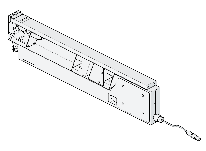
10.2.6 Linear vibratory feeder, type 3
10
Fig. 10.2 - 6 Linear vibratory feeder, type 3
Item no. 00142031-xx
Width 30 mm
Tracks per module 1, 2, 3 or 6
Maximum number of modules 2 x 20
Magazine capacity Up to 150 per stick steel magazine
depending on the component length
Stick steel magazine data 4.5 mm wide / x 6
9.5 mm wide / x 3
11 mm wide / x 2
15 mm wide / x 2
30 mm wide / x 1
Cycle time Depends on the component
Main power supply 30 VDC
10 Component handling User Manual SIPLACE S-23 HM
10.2 Technical data for the feeder modules Software Version SR.406.xx 02/00 US Edition
374
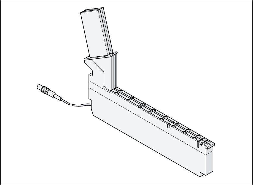
10.2.7 Bulk case feeder
10
Fig. 10.2 - 7 Bulk case feeder
Item no. 00142318-xx
Width 30 mm
Tracks per module 2
Maximum number of modules 2 x 20
Magazine capacity Approx. 5000
Feeding rails 0603 / 0.45 mm high Item no. 00142321-xx
0603 / 0.80 mm high Item no. 00142322-xx
0805 / 0.45 mm high Item no. 00142323-xx
0805 / 0.60 mm high Item no. 00142324-xx
0805 / 0.85 mm high Item no. 00142325-xx
0805 / 1.25 mm high Item no. 00142326-xx
Minimelf Item no. 00142328-xx
Cycle time < 80 ms
Main power supply 30 VDC
Compressed air supply 2.0 bar + 0.3 bar

User Manual SIPLACE S-23 HM 10 Component handling
Software Version SR.406.xx 02/00 US Edition 10.3 Setting up the feeder modules
375
10.3 Setting up the feeder modules
10.3.1 Preparing the component table and module for set-up
Å Select the setting range for the feeder module to be used
(see Vibrator configuration).
Å Move the placement head to the waiting position and press the emergency stop button.
Å Open the protective covers.
Å Clean the contact surface for the feeder modules and the contact surface for the feeder mod-
ules on the component table.
Å Place the feeder module on the previously selected track on the component table (see Vibrator
configuration).
10.3.2 Insert the module
Å Insert the module so that the back of the module is held by the centering ball and the front is
fixed in place by the corresponding centering pin on the component table. Make sure that the
module is placed on the component table in the correct position for its width.
Å Check that the module is firmly seated on the component table.
Å Connect the module plug to the socket beneath the location.
PLEASE NOTE 10
When you connect the module, make sure that you use the right socket for the location since
the module receives the control pulse via this socket. The feeder module may not work cor-
rectly if it is not connected to the right socket. 10
Å Close the protective covers and switch the control on again.
Å Carry out a refill check if necessary.
Å Continue placement.