SIPLACE S-23 HM - 第385页
User Manual SIPLACE S-23 HM 11 Station extensions / hardware Software Version SR.406.xx 02/00 US Edition 11.1 Nozzle changer for the 12-segment revolver head 385 1 1 St ation extensions / hardware 1 1 .1 Nozzle changer f…
10 Component handling User Manual SIPLACE S-23 HM
10.6 Component table, mobile Software Version SR.406.xx 02/00 US Edition
384
10.6.3 Docking the component table
WARNING 10
Check that the placement head is outside the range of the component table. 10
CAUTION 10
When docking the component table, ensure that the table bed is in its top end position and the
bracket (item 7) is folded up. 10
Å Cut off the empty tapes for the feeder modules.
Å Make sure that the contact surface (item 10) for the component table bed is clean.
Å CAREFULLY push the component table into the placement system.
Å Connect the compressed air supply (item 3).
Å Plug in the control cable (item 1).
Å Plug in the power cable (item 2) for the component table.
Å Pull the two actuating tubes (item 6) towards you at the same time and then lower the bracket
(item 7) in order to be able to lower the component table bed.
Å Check that the centring holes in the component table bed lie precisely over the centering pins
of the placement system.
Å Hold down the button (item 5) until the component table bed reaches its top end position.
Å Release the button and the component table bed will descend.
Å Ensure that the centring pins engage in the centring holes in the component table bed and that
the component table bed is fully lowered.
Å Fold up the bracket (item 7) of the component table.
Å Lock the two horizontal tensioners (item 11).
Å Close the side screens and protective cover.
Å Press the Start button to start the placement system.
10
10
10

User Manual SIPLACE S-23 HM 11 Station extensions / hardware
Software Version SR.406.xx 02/00 US Edition 11.1 Nozzle changer for the 12-segment revolver head
385
11 Station extensions / hardware
11.1 Nozzle changer for the 12-segment revolver head
11.1.1 Overview
The placement system is supplied as standard with two revolver heads. As an option, a nozzle
changer can be installed for each revolver head. 11
The nozzle changer consists of at least one, and up to seven magazines, each with twelve nozzle
garages (see Fig. 11.1 - 1). The magazines are seated on a common support and each magazine
is centered using two parallel pins and fixed in place with a screw. 11
11.1.2 Technical data - nozzle changer for the 12-segment revolver head
11
Nozzle changer for the 12-segment revolver head
Dimensions (length x width x height) 560 mm x 60 mm x 46 mm
Number of nozzle garages Min. 12 / max. 84
Nozzle types 9xx
Time required to open and close the locking plate < 200 ms
Capacity of the reject box Approx. 50 nozzles
Pneumatic circuit Compressed air line 5.3 bar
11 Station extensions / hardware User Manual SIPLACE S-23 HM
11.1 Nozzle changer for the 12-segment revolver head Software Version SR.406.xx 02/00 US Edition
386
11
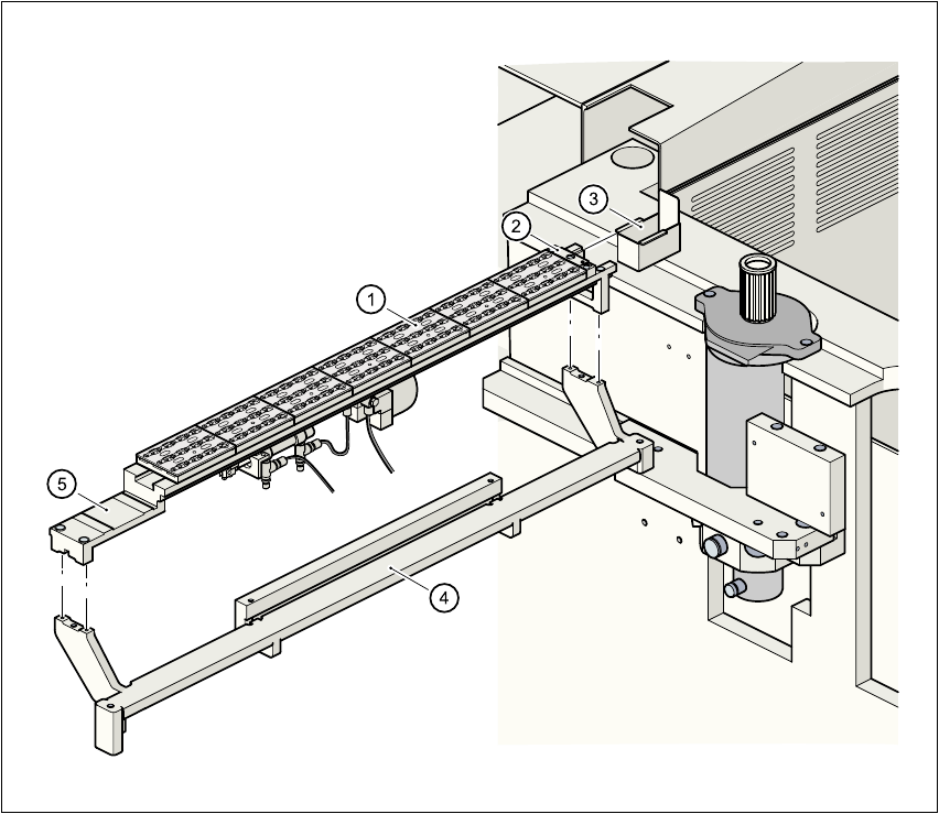
Fig. 11.1 - 1 Nozzle changer overview - revolver head
11
(1) Magazine (2) Nozzle discarding device
(3) Container for discarded nozzles (4) Nozzle changer base
(5) Nozzle changer support 11