SIPLACE S-23 HM - 第398页
11 Station extensions / hardware User Manual SIPLACE S-23 HM 11.3 Dual conveyor Software Version SR.406.xx 02/00 US E dition 398 1 1.3.9 T e chnical dat a for the dual conveyor 11 1 1. 3.10 Maint enance The indiv idual c…

User Manual SIPLACE S-23 HM 11 Station extensions / hardware
Software Version SR.406.xx 02/00 US Edition 11.3 Dual conveyor
397
11.3.7 Synchronous conveyor mode
11.3.7.1 Description
In synchronous mode, two PCBs of the same size are moved into the placement position at the
same time. They must be processed as a single cluster. 11
This enables the top and bottom of a PCB to be processed on a single line. This reduces the time
needed to transport the PCBs, since two PCBs are always transported at the same time. 11
11.3.7.2 Function
PCBs on transport tracks 1 and 2 are moved synchronously (i.e. the conveyor belts are indepen-
dent of one another, but are controlled synchronously) on the conveyor sections. The components
to be placed for transport track 1 and 2 must be organized as a cluster in two circuit images (see
the line computer operating instructions). 11
If only one transport track (or center conveyor) is occupied at the start of the placement sequence,
the circuit image for this conveyor section is identified as "do not place". 11
11.3.8 Controlling the dual conveyor with the Single functions menu
Control of the dual conveyor and the Single functions menu are described in section 5 of this user
manual. 11
11.3.8.1 Automatic width adjustment on the dual conveyor
PLEASE NOTE 11
The conveyor setpoint width relates to both conveyor belts. When the command is received, the
conveyor belts are set to the setpoint width one after another.
Automatic width adjustment is deactivated when "synchronous conveyor" is selected. 11

11 Station extensions / hardware User Manual SIPLACE S-23 HM
11.3 Dual conveyor Software Version SR.406.xx 02/00 US Edition
398
11.3.9 Technical data for the dual conveyor
11
11.3.10 Maintenance
The individual conveyor belts and the additional lifting table require the same maintenance as the
standard conveyor. Each conveyor belt must be maintained as described in the maintenance in-
structions. 11
PCB format
50 mm x 50 mm to 460 mm x 216 mm
2" x 2" to 18" x 8.5"
PCB thickness 0.3 mm to 4.5 mm
Max. PCB warpage
On top: 4.5 mm - PCB thickness
On bottom: 0.3 mm + PCB thickness
Clearance on PCB underside 25 mm (standard), 40 mm (option)
PCB transport height
830 ± 15 mm (standard)
900 ± 15 mm (option)
930 ± 15 mm (option)
950 ± 15 mm (SMEMA option)
Type of interface Siemens (standard), SMEMA (option)
Component-free handling edge 3 mm
PCB changeover time 2.5 s
Fixed conveyor edge Right (standard), left (option)
Components on each conveyor Synchronous: same or different, asynchronous: same
PCB width on each conveyor Synchronous: different, asynchronous: same
Ink spot recognition Synchronous: not possible, asynchronous: possible
Automatic width adjustment Synchronous: not possible, asynchronous: possible
User Manual SIPLACE S-23 HM 11 Station extensions / hardware
Software Version SR.406.xx 02/00 US Edition 11.4 PCB barcode
399
11.4 PCB barcode
11.4.1 Overview
The PCB barcode reader is used to automatically record and decode barcodes on PCBs. The
PCB barcode reader sends the read data via its serial interface to the machine controller for fur-
ther processing. 11
The PCB barcode readers are installed on the input side of the placement machine, above and
below the PCB conveyor, so that barcode labels on the topside and underside of the PCBs can
be read.
One or two PCB barcode readers may be retrofitted in order to read the topside and underside of
the PCB on the transport track. 11
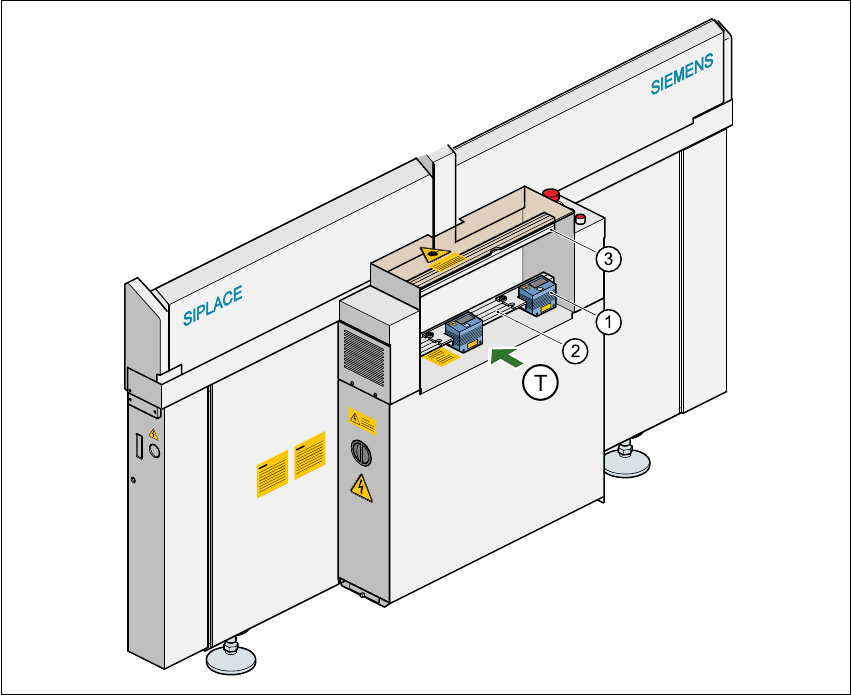
Fig. 11.4 - 1 Position of the modules on the input side of the placement machine
(1) Barcode reading head
(2) Profiled rail for ‘underside’ PCB barcode reader
(3) Profiled rail for ‘topside’ PCB barcode reader