SIPLACE S-23 HM - 第400页
11 Station extensions / hardware User Manual SIPLACE S-23 HM 11.4 PCB barcod e Software Version SR.406.xx 02/00 US Edition 400 The PCB barcode readers a re fixed to the t op and botto m prof iled rail using r etainers. T…
User Manual SIPLACE S-23 HM 11 Station extensions / hardware
Software Version SR.406.xx 02/00 US Edition 11.4 PCB barcode
399
11.4 PCB barcode
11.4.1 Overview
The PCB barcode reader is used to automatically record and decode barcodes on PCBs. The
PCB barcode reader sends the read data via its serial interface to the machine controller for fur-
ther processing. 11
The PCB barcode readers are installed on the input side of the placement machine, above and
below the PCB conveyor, so that barcode labels on the topside and underside of the PCBs can
be read.
One or two PCB barcode readers may be retrofitted in order to read the topside and underside of
the PCB on the transport track. 11
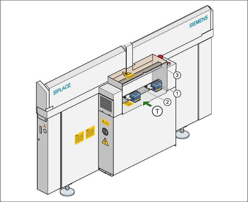
Fig. 11.4 - 1 Position of the modules on the input side of the placement machine
(1) Barcode reading head
(2) Profiled rail for ‘underside’ PCB barcode reader
(3) Profiled rail for ‘topside’ PCB barcode reader
11 Station extensions / hardware User Manual SIPLACE S-23 HM
11.4 PCB barcode Software Version SR.406.xx 02/00 US Edition
400
The PCB barcode readers are fixed to the top and bottom profiled rail using retainers. These can
be positioned as required on the profiled rails, and aligned with respect to the barcode labels. De-
pending on the position of the barcode strips, the barcode reader can be attached in a few simple
steps so that the strips can be read parallel to or across the PCB transport direction. 11
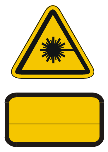
11.4.2 Laser safety instructions
Laser radiation 11
The radiation from the laser diode (infrared or IR
light) of the PCB barcode reader is harmful to the
human eye, 11
Åso you should never look into the laser beam.
ÅNever direct the PCB barcode reader into other
people’s eyes.
ÅWhen installing the barcode reader, make sure
that the laser beam cannot be not reflected during
use.
If you open the housing during use, the scanning cy-
cle will continue, and the laser diode will continue to
switch on. 11
The laser beam output at the barcode template win-
dow does not exceed 1.0 mW. The PCB barcode
reader thus conforms to protection class 2. 11
Fig. 11.4 - 2 Laser safety instructions for the PCB barcode reader
11.4.3 Functional description
11.4.3.1 PCB barcode reader for the single conveyor
The SIPLACE PCB barcode reader supports the flexible manufacture of SMD products, and in-
creases placement reliability. It recognizes all the code types conventionally used in industrial ap-
plications. 11
The laser scanner reads the barcode label on the topside or underside of each incoming PCB as
they are transported onto the input conveyor. The barcode data enables the line computer to au-
tomatically select the correct barcode allocation list from the previously created barcode assign-
ment list, and sends it to the station. If a barcode filter was defined, only the data that is identified
as relevant will be compared in the barcode. This procedure is carried out time neutrally during
placement of the PCB already in the machine. If several PCBs with the same barcode enter in
succession, the program is only transferred the first time. The following requirements apply to all
products to be produced using the PCB barcode: 11
ATTENTION
LASER RADIATION
DO NOT LOOK INTO THE BEAM
CLASS 2 LASER PRODUCT
EN 60825 1991
Max. output radiation: 1.0 mW
Wavelength: 670 nm

User Manual SIPLACE S-23 HM 11 Station extensions / hardware
Software Version SR.406.xx 02/00 US Edition 11.4 PCB barcode
401
– The component set-up must be identical on all the machines on the line
– All PCBs must be of the same width
11.4.3.2 PCB barcode reader for the dual conveyor
On the dual conveyor, the PCB barcode is only used to transfer the barcode via the GEM interface.
This is absolutely essential since the placement program cannot be supplied automatically. 11
11.4.4 Technical data
* This value can only be achieved if the barcode label on the PCB passes through the scanner
perpendicular to the machine’s transport direction. 11
** The position of the barcode scanner on the input conveyor can be easily adjusted, depending
on where the barcode labels are located on the PCBs. 11
Max. component sizes for the single con-
veyor
Standard: (L x W) up to 460 mm x 460 mm
Option: (L x W) up to 508 mm x 460 mm
(same width for all the jobs in a sequence)
Label dimensions Stroke width B: 0.19 < B ≤ 0.3 mm
(corresponds to high and medium density)
Stroke length: ≥ 4 mm*
Length of the barcode template window ≤ 90 mm
Label alignment on the PCB ** Parallel or perpendicular with respect to the
PCB transport direction, as close as possible to the fixed
transport side.
Label colors (contrast ratio > 70% to DIN
66236)
Coding: black, dark green, dark blue
Background: white, beige, yellow, orange
Code types Code 39, Code 128 / EAN 128,
Codabar, 2/5 IATA 2/5 industrial,
2/5 interleaved, UPC, EAN,
Pharma Code, EAN Addendum
(others available upon request)
Complete barcode up to 25 digits (a barcode filter can also be defined)
Laser scanner safety Laser diode 670 nm (red) / 1 mW
Laser protection class 2, type of protection IP65
Station and line software Version 405.xx or later
Read in / evaluation duration time neutral (T ≤ 1 s), since it is carried out in parallel to
placement of the previous PCB