SIPLACE S-23 HM - 第402页
11 Station extensions / hardware User Manual SIPLACE S-23 HM 11.4 PCB barcod e Software Version SR.406.xx 02/00 US Edition 402 1 1.4.5 Assembly options for the PCB barcode reader Fig. 1 1.4 - 3 Assembly options for the P…

User Manual SIPLACE S-23 HM 11 Station extensions / hardware
Software Version SR.406.xx 02/00 US Edition 11.4 PCB barcode
401
– The component set-up must be identical on all the machines on the line
– All PCBs must be of the same width
11.4.3.2 PCB barcode reader for the dual conveyor
On the dual conveyor, the PCB barcode is only used to transfer the barcode via the GEM interface.
This is absolutely essential since the placement program cannot be supplied automatically. 11
11.4.4 Technical data
* This value can only be achieved if the barcode label on the PCB passes through the scanner
perpendicular to the machine’s transport direction. 11
** The position of the barcode scanner on the input conveyor can be easily adjusted, depending
on where the barcode labels are located on the PCBs. 11
Max. component sizes for the single con-
veyor
Standard: (L x W) up to 460 mm x 460 mm
Option: (L x W) up to 508 mm x 460 mm
(same width for all the jobs in a sequence)
Label dimensions Stroke width B: 0.19 < B ≤ 0.3 mm
(corresponds to high and medium density)
Stroke length: ≥ 4 mm*
Length of the barcode template window ≤ 90 mm
Label alignment on the PCB ** Parallel or perpendicular with respect to the
PCB transport direction, as close as possible to the fixed
transport side.
Label colors (contrast ratio > 70% to DIN
66236)
Coding: black, dark green, dark blue
Background: white, beige, yellow, orange
Code types Code 39, Code 128 / EAN 128,
Codabar, 2/5 IATA 2/5 industrial,
2/5 interleaved, UPC, EAN,
Pharma Code, EAN Addendum
(others available upon request)
Complete barcode up to 25 digits (a barcode filter can also be defined)
Laser scanner safety Laser diode 670 nm (red) / 1 mW
Laser protection class 2, type of protection IP65
Station and line software Version 405.xx or later
Read in / evaluation duration time neutral (T ≤ 1 s), since it is carried out in parallel to
placement of the previous PCB
11 Station extensions / hardware User Manual SIPLACE S-23 HM
11.4 PCB barcode Software Version SR.406.xx 02/00 US Edition
402
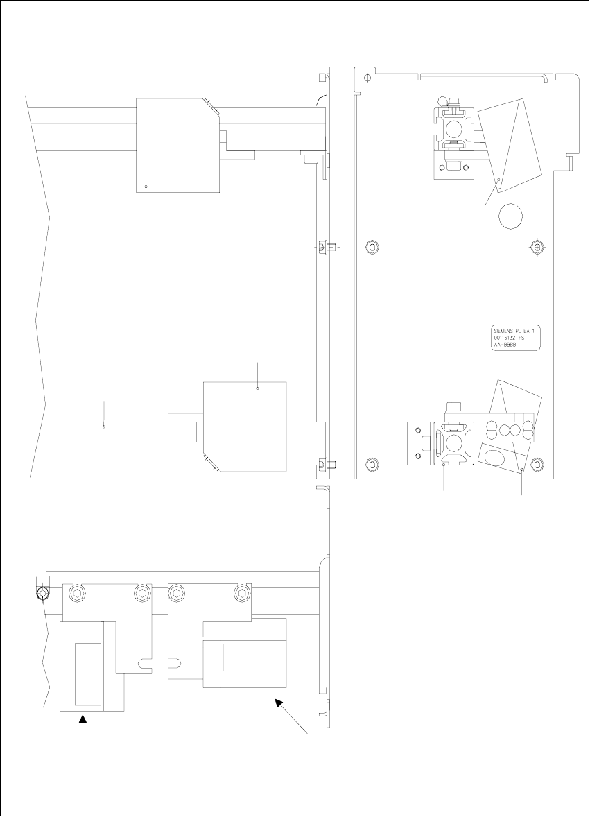
11.4.5 Assembly options for the PCB barcode reader
Fig. 11.4 - 3 Assembly options for the PCB barcode reader
Front view 11 Side view 11
Assembly for
PCB barcode on
the PCB topside
Assembly for
PCB barcode on
the PCB underside
Plan view 11
Position of the PCB barcode
reader if the barcode strip
is aligned parallel to
the PCB transport direction.
Position of the PCB barcode
reader if the barcode strip
is aligned perpendicular to
the PCB transport direction.
Profiled rail
PCB barcode
reader ‘topside’
PCB barcode
reader ‘underside’
Profiled rail
User Manual SIPLACE S-23 HM 11 Station extensions / hardware
Software Version SR.406.xx 02/00 US Edition 11.4 PCB barcode
403
11.4.6 Configuring the PCB barcode reader
The PCB barcode reader is configured using barcode labels. The retrofit kit contains the program
for defining these labels. 11
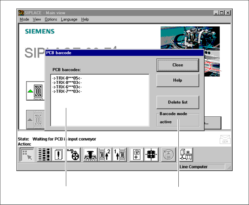
11.4.7 Displaying the PCB barcode
This menu is used to display in a list box the last barcode to be read by the PCB barcode reader.11
The box also indicates if the barcode was read incorrectly, a start signal was received, the wrong
format was identified or no data was available. 11
Å Select the PCB barcode submenu under Options from the menu bar.
. 11
Fig. 11.4 - 4 Displaying the PCB barcode
(1) List box
(2) Status display
Å To delete the list, click on the Delete list button.
111
211