SIPLACE S-23 HM - 第410页
11 Station extensions / hardware User Manual SIPLACE S-23 HM 11.5 Ceramic subs trate centering Software Version SR.406.xx 02/00 US Edition 410 Fiducial s tructure 11 Recommenda tion 1 Fiduci al structu re Black resisti v…
User Manual SIPLACE S-23 HM 11 Station extensions / hardware
Software Version SR.406.xx 02/00 US Edition 11.5 Ceramic substrate centering
409
PLEASE NOTE
Oblique lighting can only be used on the “sub-gantry camera”. 11
11.5.5.2 Fiducial mark recommendation for ceramic substrates
The contrast between the carrier package material and the circuit-board conductor layer is gener-
ally very small with ceramic substrates. The fiducials must therefore be selected with regard to
certain criteria concerning the fiducial shape and structure. Recommended fiducial shapes and
structures are given below. 11
Fiducial shape 11
We recommend a rectangle or square with an edge length of > 1 mm, and a clearance
of > 0.5 mm. 11
11
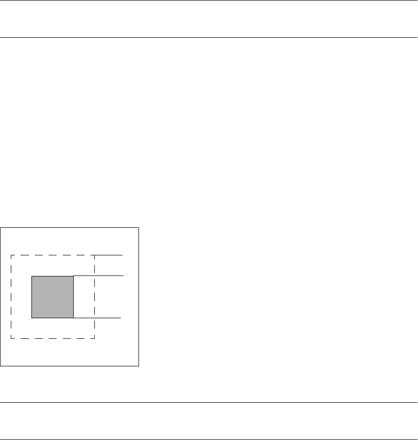
Fig. 11.5 - 4 Recommended fiducial shape
PLEASE NOTE
Single crosses are also suitable, but they take up more space. 11
0.5 mm
1.0 mm

11 Station extensions / hardware User Manual SIPLACE S-23 HM
11.5 Ceramic substrate centering Software Version SR.406.xx 02/00 US Edition
410
Fiducial structure 11
Recommendation 1
Fiducial structure Black resistive paste as the background, with conductive paste printed on it as
the fiducial.
Recommendation Background 0.75 mm larger than the fiducial on all sides.
Method of illumination Normal light
Advantage Good contrast, good sharpness;
Reference Circuit-board conductor layer
Assessment This combination gives the best results. Highly recommended.
Recommendation 2
Fiducial structure Fiducial made from circuit-board conductor material, e.g. 6119, and overprinted
with passivated glass 4330.
Method of illumination Oblique light
Advantage No additional steps required
Reference Circuit-board conductor layer
Assessment Fiducials are less sharp than for recommendation 1. Recommended.
Recommendation 3
Fiducial structure Fiducials made from circuit-board conductor layer against a free ceramic back-
ground.
Method of illumination Oblique or normal light (depending on the paste)
Advantage No additional steps required
Reference Circuit-board conductor layer
Note Fiducials are less sharp than for recommendation 2.
The fiducial image depends on the surrounding free surface. It may be neces-
sary to teach every circuit separately.
Assessment Recommended under certain conditions.
User Manual SIPLACE S-23 HM 11 Station extensions / hardware
Software Version SR.406.xx 02/00 US Edition 11.6 Feeder position recognition
411
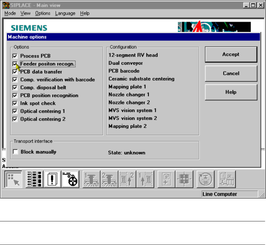
11.6 Feeder position recognition
If the feeder modules are equipped with positioning fiducials, the fiducials can be measured.
If the "Conveyor position detection" function has been selected on the line computer, the function
will also appear in the Machine options. It can then be activated or deactivated at each station.
11
Fig. 11.6 - 1 Feeder position recognition
PLEASE NOTE 11
The "Feeder position recognition" function is always deactivated when the station is switched on. 11
If a track has been entered in the cluster data, the PCB camera on the feeder module will ap-
proach the position of the centering fiducial. Any centering fiducial offset determined during the
measurement will then be assigned to this track and added to the pick-up position during the pick-
up operation. 11