SIPLACE S-23 HM - 第411页
User Manual SIPLACE S-23 HM 11 Station extensions / hardware Software Version S R.406.xx 02/00 US Edition 11.6 Feeder position recognition 411 1 1 .6 Feeder position reco gnition If the fe eder modu les a re equip ped wi…

11 Station extensions / hardware User Manual SIPLACE S-23 HM
11.5 Ceramic substrate centering Software Version SR.406.xx 02/00 US Edition
410
Fiducial structure 11
Recommendation 1
Fiducial structure Black resistive paste as the background, with conductive paste printed on it as
the fiducial.
Recommendation Background 0.75 mm larger than the fiducial on all sides.
Method of illumination Normal light
Advantage Good contrast, good sharpness;
Reference Circuit-board conductor layer
Assessment This combination gives the best results. Highly recommended.
Recommendation 2
Fiducial structure Fiducial made from circuit-board conductor material, e.g. 6119, and overprinted
with passivated glass 4330.
Method of illumination Oblique light
Advantage No additional steps required
Reference Circuit-board conductor layer
Assessment Fiducials are less sharp than for recommendation 1. Recommended.
Recommendation 3
Fiducial structure Fiducials made from circuit-board conductor layer against a free ceramic back-
ground.
Method of illumination Oblique or normal light (depending on the paste)
Advantage No additional steps required
Reference Circuit-board conductor layer
Note Fiducials are less sharp than for recommendation 2.
The fiducial image depends on the surrounding free surface. It may be neces-
sary to teach every circuit separately.
Assessment Recommended under certain conditions.
User Manual SIPLACE S-23 HM 11 Station extensions / hardware
Software Version SR.406.xx 02/00 US Edition 11.6 Feeder position recognition
411
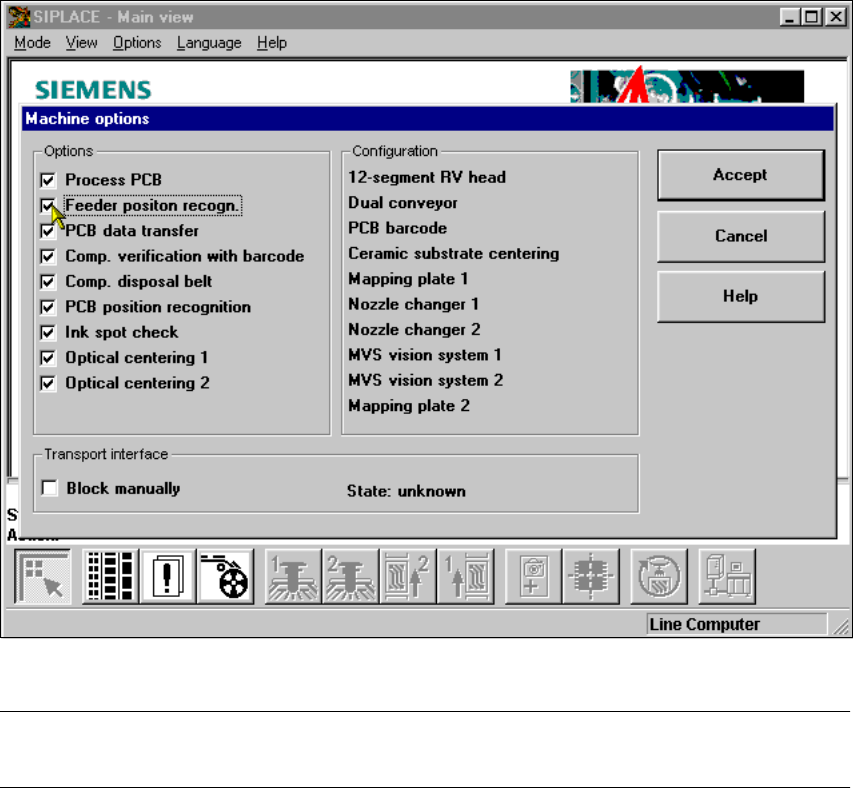
11.6 Feeder position recognition
If the feeder modules are equipped with positioning fiducials, the fiducials can be measured.
If the "Conveyor position detection" function has been selected on the line computer, the function
will also appear in the Machine options. It can then be activated or deactivated at each station.
11
Fig. 11.6 - 1 Feeder position recognition
PLEASE NOTE 11
The "Feeder position recognition" function is always deactivated when the station is switched on. 11
If a track has been entered in the cluster data, the PCB camera on the feeder module will ap-
proach the position of the centering fiducial. Any centering fiducial offset determined during the
measurement will then be assigned to this track and added to the pick-up position during the pick-
up operation. 11
11 Station extensions / hardware User Manual SIPLACE S-23 HM
11.7 PCB data transfer Software Version SR.406.xx 02/00 US Edition
412
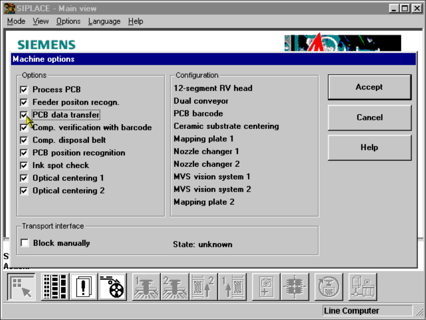
11.7 PCB data transfer
11.7.1 Functional description
The ’Machine options’ menu contains a ’PCB data transfer’ option. The aim of this function is to
increase the placement system’s performance on the line. To do this, an entire PCB is measured
at the
first
placement station and the associated fiducial, single circuit, ink spot, etc. data is deter-
mined, saved and sent to the next station. At subsequent stations, the data is then determined for
two fiducial positions only. These two fiducial positions are then used to correct the position for the
PCB to be processed at each station. It is thus not necessary to measure the entire PCB again,
together with its single circuits, ink spots etc. 11
11.7.2 Activating the ’PCB data transfer’ option
11
Fig. 11.7 - 1 Machine option: PCB data transfer