SIPLACE S-23 HM - 第49页
User Manual SIPLAC E S-23 HM 1 Introduction, technical dat a Software Vers ion SR.406.xx 02/00 US Edition 1. 15 Overv iew of the modules - P CB conveyor 49 1.15 Ov erview of the modules - PCB conveyor 1.15.1 Structure of…

1 Introduction, technical data User Manual SIPLACE S-23 HM
1.14 Overview of the modules - vision systems Software Version SR.406.xx 02/00 US Edition
48
1.14.2 Technical data - PCB vision module
Fiducials Up to 3 per placement program
Local fiducials Up to 2 per component (may be of different types)
Library size Up to 255 fiducial types - system fiducials ≥ 249
Image processing Gray scale-based correlation
Illumination method Front-lighting
Recognition time per fiducial/ink spot 0.4 s
Field of vision 5.7 mm x 5.7 mm
User Manual SIPLACE S-23 HM 1 Introduction, technical data
Software Version SR.406.xx 02/00 US Edition 1.15 Overview of the modules - PCB conveyor
49
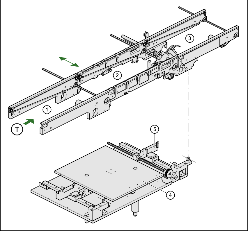
1.15 Overview of the modules - PCB conveyor
1.15.1 Structure of the PCB conveyor
The placement system is supplied with a single conveyor as standard. A dual conveyor is avail-
able as an option. 1
The left or the right side of the PCB conveyor can be used as the stationary side, as required. 1
1
Fig. 1.15 - 1 PCB transport - single conveyor
(1) Input conveyor (2) Center conveyor
(3) Output conveyor (4) Lifting table
(5) Width adjustment T Direction of PCB transport 1

1 Introduction, technical data User Manual SIPLACE S-23 HM
1.15 Overview of the modules - PCB conveyor Software Version SR.406.xx 02/00 US Edition
50
The conveyor belts are driven by DC motors. The lifting table near the center conveyor clamps the
PCBs in position. The width of the PCB conveyor can be adjusted either 1
– via the menu or
– using the line computer.
1
1.15.2 Technical data – single conveyor
1
1
1.15.3 Technical data – dual conveyor
1
PCB format 50mm x 50mm to 460mm x 460mm
2" x 2" to 18" x 18"
Optionally: up to 508mm x 460mm
up to 20" x 18 "
PCB thickness 0.5mm to 4.5mm
Max. PCB warpage On top: 4.5mm - PCB thickness
On bottom: 0.5mm + PCB thickness
Clearance on PCB underside 25mm (standard), 40mm (option)
PCB transport height 830mm ± 15mm (standard)
900mm ± 15mm (option)
930mm ± 15mm (option)
950mm ± 15mm (SMEMA: optional)
Fixed conveyor edge Right (standard), left (optional)
Type of interface Siemens (standard), (SMEMA: optional)
Component-free handling edge 3mm
PCB changeover time 2.5 s
PCB format 50mm x 50mm to 460mm x 216mm
2" x 2" to 18" x 8.5"
Optionally: up to 508mm x 216mm
up to 20" x 8.5 "
PCB thickness 0.5mm to 4.5mm
Max. PCB warpage On top: 4.5mm - PCB thickness
On bottom: 0.5mm + PCB thickness
Clearance on PCB underside 25mm (standard), 40mm (option)