SIPLACE S-23 HM - 第75页
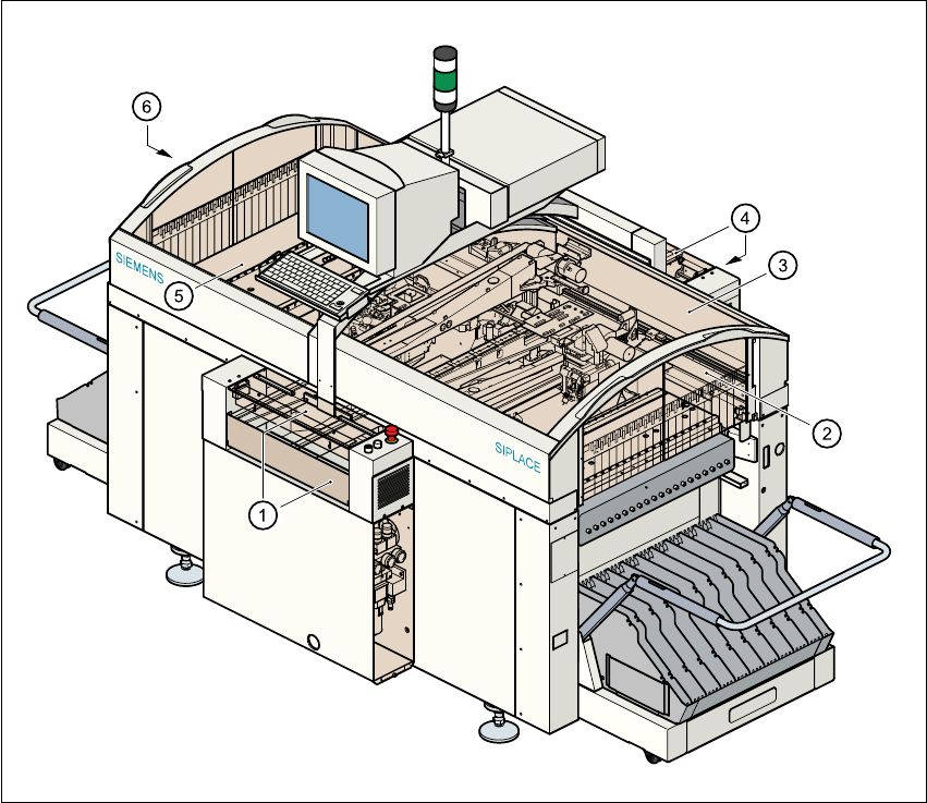
User Manual SIPLAC E S-23 HM 2 Operational Safety Software Version SR.406.xx 02/00 US Edition 2.2 Safety equipment 75 2.2 Safe ty equipme nt 2.2.1 Pro tective c over s 2 Fig. 2.2 - 1 SIPLACE S-23 HM safety equipment Key …
2 Operational Safety User Manual SIPLACE S-23 HM
2.1 Safety instructions Software Version SR.406.xx 02/00 US Edition
74
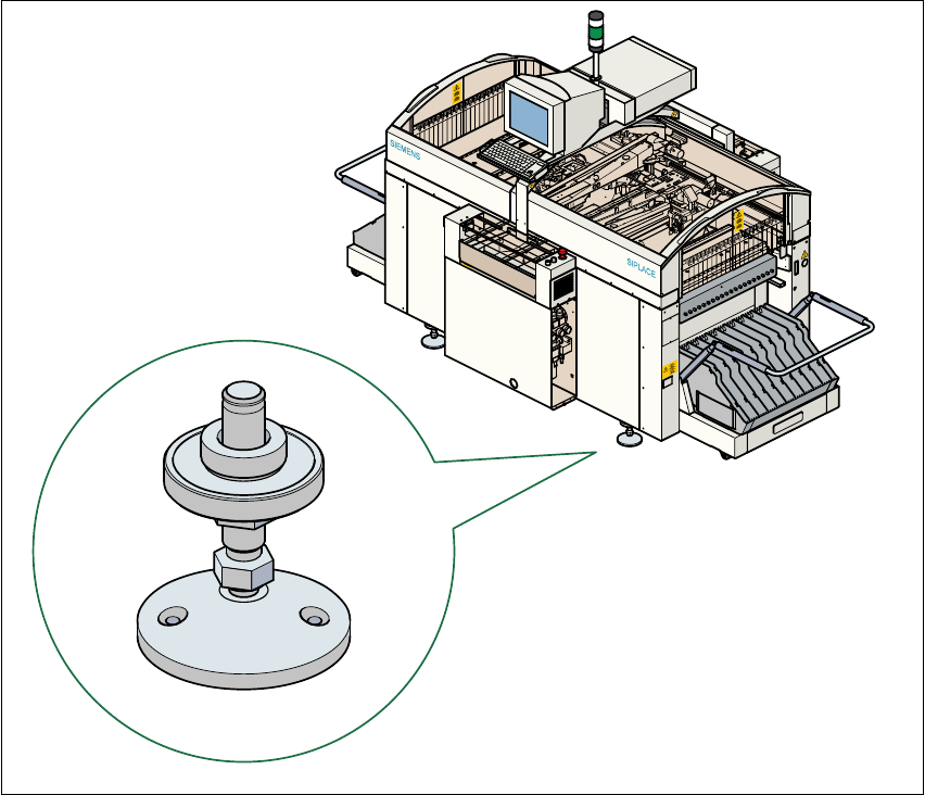
2.1.12 Securing the placement machine to prevent it slipping
In areas with an earthquake risk, it is essential to secure the placement machine to prevent it slip-
ping. 2
Two holes for M8 bolts are provided in the machine feet for this purpose. 2
Å Use the bolts to fix the placement machine to the floor as shown in the diagram below.
Fig. 2.1 - 12 Securing the placement machine to prevent it slipping
2
User Manual SIPLACE S-23 HM 2 Operational Safety
Software Version SR.406.xx 02/00 US Edition 2.2 Safety equipment
75
2.2 Safety equipment
2.2.1 Protective covers
2
Fig. 2.2 - 1 SIPLACE S-23 HM safety equipment
Key to Fig. 2.2 - 1
(1) Cover and guard on the input belt
(2) Safety panels, righthand side
(3) Protective cover
(4) Cover and guard on the output conveyor
(5) Protective cover
(6) Safety panels, lefthand side
2 Operational Safety User Manual SIPLACE S-23 HM
2.2 Safety equipment Software Version SR.406.xx 02/00 US Edition
76
2.2.1.1 General
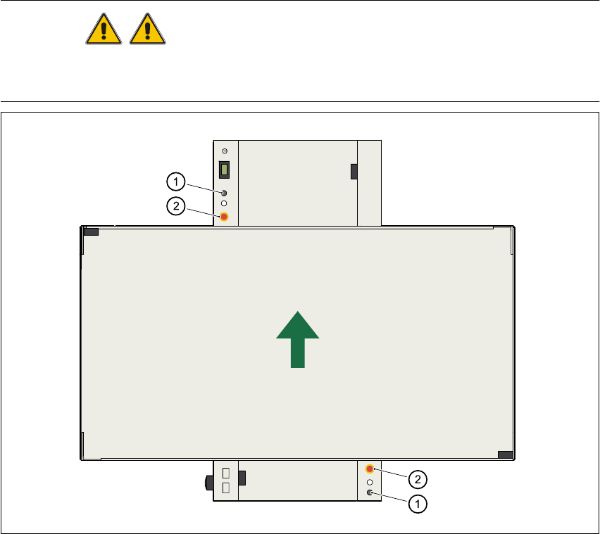
The gantry positioning range is covered by two protective covers. If you want to open the protec-
tive covers, first press the Stop button (item 1 in Fig. 2.2 - 2) or the emergency stop mushroom-
head push-button (item 2 in Fig. 2.2 - 2). The power to the gantry axes will be switched off and the
gantries will stop immediately. 2
If you open one of the protective covers or a guard on the incoming or outgoing conveyor, the
power to the gantry axes will be switched off and they will stop immediately. 2
If the key switch is closed (position I), you can continue to pace the star at reduced speed while
the protective covers are open. 2
Placement will stop if you press the emergency stop button. You can then either cancel or continue
placement of the PCB. The protective covers at the sides can be opened in order to refill with com-
ponents when the machine has stopped. 2
WARNING
The protective covers must only be opened, with the key switch closed (position I), by appropri-
ately qualified and trained personnel. 2
Fig. 2.2 - 2 Stop and emergency stop mushroom-head push-buttons
(1) Stop button (2)EMERGENCY STOP mushroom-head push-button 2