Specification SIPLACE CF-Medium - 第3页
2 Medium Volume F lexible P laceme nt of Large and C omp lex C ompone nt s SIPL ACE CF SIP LACE CF with Waffle Pac k Changer
1
Subject to change
without notice
Edition 2
0505-CF-e
Order No
A10002-P141-T5-X-7600
Machine Description 3
Line Design 4
Placement Heads 5
6-Nozzle Collect & Place Head for High Speed
Component Placement
Pick & Place Head for High End / High Accuracy
Component Placement
Placement Accuracy
Component Range
Nozzle Changer
PCB Conveyor 9
Component Supply 10
Changeover Table
Tape Feeder
Bulk Case Feeders
Stick Magazine Feeders
Guard for Feeder Locations
Manual Trays
Waffle Pack Changer
Component Bar Code Scanner for Set-Up and Refill Check (Option)
SIPLACE External Set-Up Station (Option)
Vision Sensor Technology 18
PCB Vision Module
PCB Position Recognition
Bad Board Recognition
Position Recognition of Feeder
Standard Component Vision Module for the
6-Nozzle Collect & Place Head
Standard Component Vision Module for the Pick & Place Head
Machine Criteria 22
Mapping (Option)
SIPLACE Software Architecture 23
Line Programming System
Station Computer
Technical Data 24
Signal Interfaces
Connections
Dimensions and Set-Up Conditions
Transporting and Commissioning
Possible Machine Configuration 29
Medium Volume Flexible Placement of
Large and Complex Components
SIPLACE CF
2
Medium Volume Flexible Placement of
Large and Complex Components
SIPLACE CF
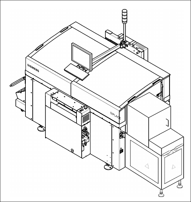
SIPLACE CF with Waffle Pack Changer

3
Description
SIPLACE CF placement machines
combine Pick & Place Head and
Collect & Place Head to unite high
precision with high speed.
While the PCB is transferring from
the buffer zone to the stationary
population zone, the Collect &
Place Head is already picking up
components.
As soon as the PCB´s exact posi-
tion is determined by the PCB
camera, the Collect & Place Head
will move into the population zone
and perform its placement se-
quence. This step will be repeated
until all components assigned to
the Collect & Place Head are
placed. When the Collect & Place
Head has finished, the Pick &
Place Head begins picking up and
placing the components assigned
to it, until the board is complete.
This award winning SIPLACE
concept has distinct advantages:
Component tapes can be re-
plenished by splicing a new reel
of components to the end of a
depleting reel. This eliminates
machine stoppage due to com-
ponent replenishment.
Stationary, vibration-free feed-
ers ensure a reliable pick-up of
even the smallest components
(e.g., 0201).
Populating a stationary PCB also
prevents components from
shifting during placement.
Automatic width adjustment, auto-
matic nozzle changers, easy chang-
ing of feeder modules or change-
over tables, which can be replaced
within minutes, allow quick changes
of productions.
The following options are available
for the SIPLACE CF:
Additional changeover tables
enables the reduction of job set-
up time increasing machine
utilisation.
Component Bar Code Scanner
used for feeder set-up verifica-
tion.
SIPLACE CF can be ordered in two
standard configurations:
with two Changeover Tables
(SIPLACE CF) or
with one Changeover Table and
one Waffle Pack Changer
(SIPLACE CF/WPW).
Machine Description
Technical Data
Type of placement head
Pick & Place Head and
6-Nozzle Collect & Place Head
Number of gantries 1
Benchmark placement rate
a
1,800 cph (Pick & Place Head)
9,000 cph (6-Nozzle Collect & Place Head)
Component Range 0.6 x 0.3 mm
2
(0201) to 55 x 55 mm
2
Max. placement accuracy
(at 4 sigma)
a
50 µm (Pick & Place Head)
90 µm (6-Nozzle Collect & Place Head)
PCB dimensions
(L x W)
50 x 50 mm
2
to 508 x 460 mm
2
/
2" x 2" to 20" x 18"
Feeding capacity 118 tracks, 8 mm tape
Component table
Quick changeover table with integrated
wheels, reel holder, scrap bin, cutting tool,
SIPLACE Waffle Pack Changer
Types of Feeder modules Tapes, Bulk Cases, Stick Magazines,
Operating system Microsoft Windows / RMOS
Power 1,9 kW
Compr. air requirements 5 - 10 bar, 350 Nl/min, tube ¾"
Standard configuration
Nozzle changer
Feeder package
SMEMA
a) As defined in Scope of Service and Delivery SIPLACE.