Nordson_EFD_GV_Series_Operating_Manual - 第142页
GV Series Automated Dispensing Systems 142 www.nordsonefd.com info@nordsonefd.com +1-401-431-7000 Sales and service of Nordson EFD dispensing systems are available worldwide. T o Set Up the Height Sensor # Click Step Ref…
GV Series Automated Dispensing Systems
141www.nordsonefd.com info@nordsonefd.com +1-401-431-7000 Sales and service of Nordson EFD dispensing systems are available worldwide.
# Click Step Reference Image
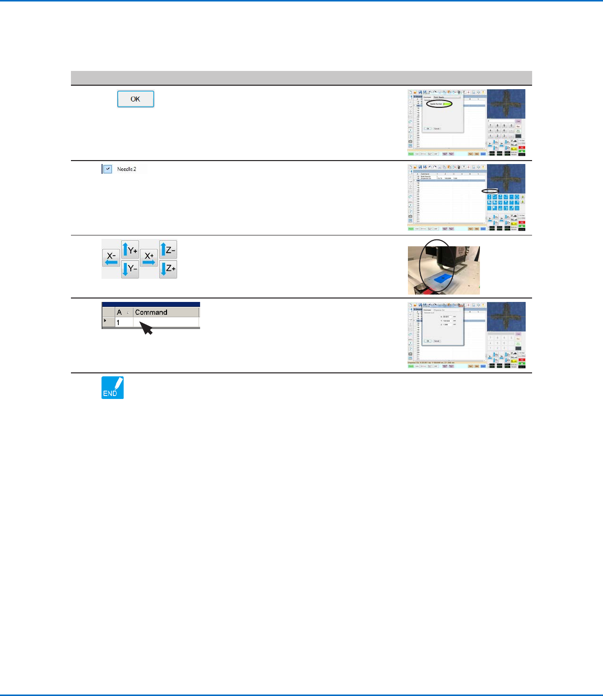
7
2 >
• Enter the number of the dispenser to
dispense from at this point in the program (in
this example, Dispenser 2).
• Click OK to save.
8
• In the Secondary View screen, right click and
check the NEEDLE 2 checkbox.
9
• Click the FOCUS icon to focus the camera.
• Jog the camera until the camera crosshairs
are centered over the desired target on the
workpiece.
10
• Insert the required commands for
Dispenser2 (for example, create arc or fills).
11
• Click END PROGRAM to end the program.
The system will dispense from Dispenser 1
or Dispenser 2 as programmed.
Appendix E, Multi-Needle Setup and Use (continued)
To Use the Multi Needle Command in a Program (continued)
GV Series Automated Dispensing Systems
142 www.nordsonefd.com info@nordsonefd.com +1-401-431-7000 Sales and service of Nordson EFD dispensing systems are available worldwide.
To Set Up the Height Sensor
# Click Step Reference Image
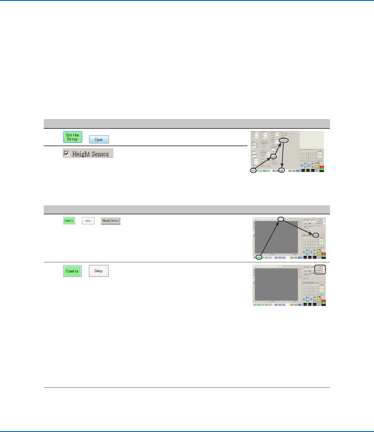
1
> >
• Click the CAMERA tab, click SETUP at the
top of the Camera screen, and then click the
HEIGHT SENSOR tab.
The Height Sensor fields appear.
2
>
• In the fields located at the top right corner of
the Height Sensor area, enter the following
values:
- Probe Output: As connected on your
system (default = 8)
- Sensor Input: As connected on your
system (default = 8)
- Detect Speed (mm/s): 5 (range = 1–20)
- Travel Limit (mm): 20 (range = 1–100)
NOTES:
• Detect Speed is how fast the Zaxis lowers
towards the workpiece after the height
sensor probe extends.
• Travel Limit is the range within which the
Zaxis moves to detect the Z-height value.
Continued on next page
AppendixF, Height Sensor Setup and Use
The optional height sensor can detect any variation from the original Z height program values from workpiece
to workpiece. If the Z height changes, the system detects the new Z height values and adjusts the program
accordingly.
PREREQUISITES
The height sensor is installed and the cable is connected to the I/O port. Refer to the instructions provided with
the height sensor.
The system is properly set up. Refer to “Setting Up and Calibrating the System (Required)” on page48.
A test workpiece is positioned on the fixture plate or work surface.
To Enable the Height Sensor
#
Click Step Reference Image
1
>
• Click the SYSTEM SETUP tab, then click
OPEN.
2
• Check HEIGHT SENSOR.
When the height sensor is enabled, the
Toggle Probe button appears in the tab bar.
GV Series Automated Dispensing Systems
143www.nordsonefd.com info@nordsonefd.com +1-401-431-7000 Sales and service of Nordson EFD dispensing systems are available worldwide.
# Click Step Reference Image
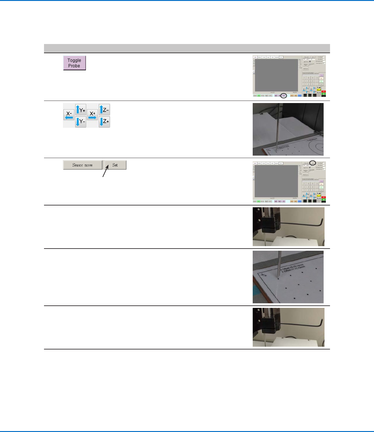
3
• Click TOGGLE PROBE.
The probe extends from the height sensor.
4
• Jog the tip to a suitable location on the
workpiece (an area that is open and will be
safe for the tip to touch) to test the height
sensor.
5
• Click SET next to Sensor Move.
6
• Use a 1.5 mm hex wrench to loosen the set
screw located inside the sensor block.
7
• Carefully grasp the probe with your fingers
and pull it down until the bottom of the
probe is about 10 mm above the workpiece.
8
• Tighten the set screw inside the sensor
block.
Continued on next page
Appendix F, Height Sensor Setup and Use (continued)
To Set Up the Height Sensor (continued)