Nordson_EFD_GV_Series_Operating_Manual - 第143页
GV Series Automated Dispensing Systems 143 www.nordsonefd.com info@nordsonefd.com +1-401-431-7000 Sales and service of Nordson EFD dispensing systems are available worldwide. # Click Step Reference Image 3 • Click TOGGLE…
GV Series Automated Dispensing Systems
142 www.nordsonefd.com info@nordsonefd.com +1-401-431-7000 Sales and service of Nordson EFD dispensing systems are available worldwide.
To Set Up the Height Sensor
# Click Step Reference Image
1
> >
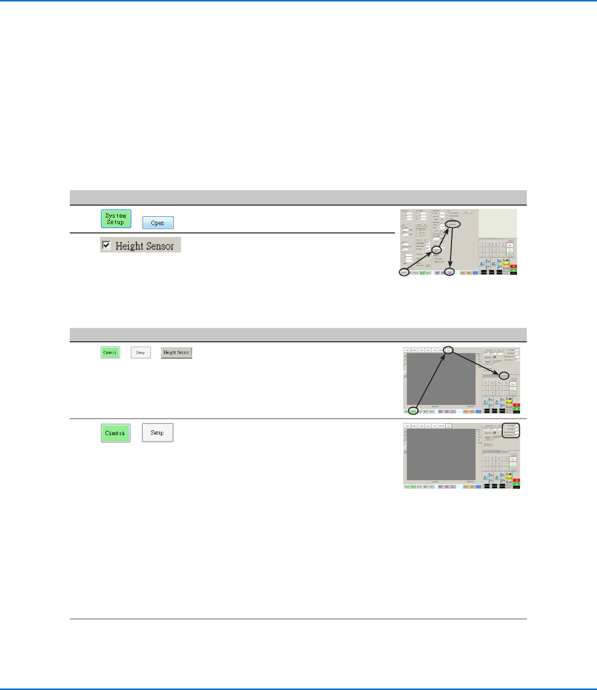
• Click the CAMERA tab, click SETUP at the
top of the Camera screen, and then click the
HEIGHT SENSOR tab.
The Height Sensor fields appear.
2
>
• In the fields located at the top right corner of
the Height Sensor area, enter the following
values:
- Probe Output: As connected on your
system (default = 8)
- Sensor Input: As connected on your
system (default = 8)
- Detect Speed (mm/s): 5 (range = 1–20)
- Travel Limit (mm): 20 (range = 1–100)
NOTES:
• Detect Speed is how fast the Zaxis lowers
towards the workpiece after the height
sensor probe extends.
• Travel Limit is the range within which the
Zaxis moves to detect the Z-height value.
Continued on next page
AppendixF, Height Sensor Setup and Use
The optional height sensor can detect any variation from the original Z height program values from workpiece
to workpiece. If the Z height changes, the system detects the new Z height values and adjusts the program
accordingly.
PREREQUISITES
The height sensor is installed and the cable is connected to the I/O port. Refer to the instructions provided with
the height sensor.
The system is properly set up. Refer to “Setting Up and Calibrating the System (Required)” on page48.
A test workpiece is positioned on the fixture plate or work surface.
To Enable the Height Sensor
#
Click Step Reference Image
1
>
• Click the SYSTEM SETUP tab, then click
OPEN.
2
• Check HEIGHT SENSOR.
When the height sensor is enabled, the
Toggle Probe button appears in the tab bar.
GV Series Automated Dispensing Systems
143www.nordsonefd.com info@nordsonefd.com +1-401-431-7000 Sales and service of Nordson EFD dispensing systems are available worldwide.
# Click Step Reference Image
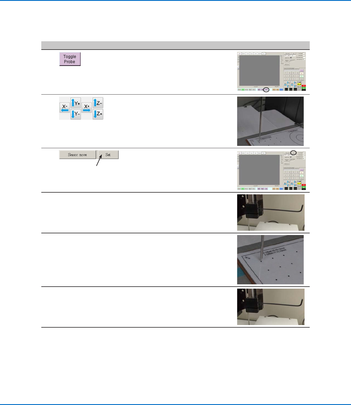
3
• Click TOGGLE PROBE.
The probe extends from the height sensor.
4
• Jog the tip to a suitable location on the
workpiece (an area that is open and will be
safe for the tip to touch) to test the height
sensor.
5
• Click SET next to Sensor Move.
6
• Use a 1.5 mm hex wrench to loosen the set
screw located inside the sensor block.
7
• Carefully grasp the probe with your fingers
and pull it down until the bottom of the
probe is about 10 mm above the workpiece.
8
• Tighten the set screw inside the sensor
block.
Continued on next page
Appendix F, Height Sensor Setup and Use (continued)
To Set Up the Height Sensor (continued)
GV Series Automated Dispensing Systems
144 www.nordsonefd.com info@nordsonefd.com +1-401-431-7000 Sales and service of Nordson EFD dispensing systems are available worldwide.
# Click Step Reference Image
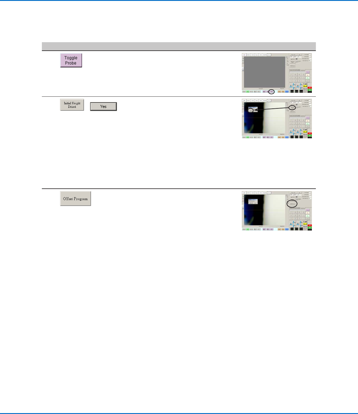
9
• Click TOGGLE PROBE to retract the probe.
10
>
• Click INITIAL HEIGHT DETECT, then click
YES to capture the Z height.
The height sensor probe touches the
workpiece surface and then shows the value
in the Current Z Height field.
The system is now ready for height sensor
detection. Do one of the following:
- Continue to the next step to update the
Z height values in the currently open
program.
- Continue to the next procedure in this
section to use this feature in a program.
11
• (Optional) To update the Z height values in
the currently open program, click OFFSET
PROGRAM.
The system checks the current Z height
by lowering and raising the probe. If the
detected Z height value is different from the
Z height values in the program, the system
prompts for confirmation to update the Z
height values. Click YES to accept the offset
value. The system automatically updates all
the Z height values in the program.
Appendix F, Height Sensor Setup and Use (continued)
To Set Up the Height Sensor (continued)