Nordson_EFD_GV_Series_Operating_Manual - 第26页
GV Series Automated Dispensing Systems 26 www.nordsonefd.com info@nordsonefd.com +1-401-431-7000 Sales and service of Nordson EFD dispensing systems are available worldwide. Concepts Before creating any programs, make su…
GV Series Automated Dispensing Systems
25www.nordsonefd.com info@nordsonefd.com +1-401-431-7000 Sales and service of Nordson EFD dispensing systems are available worldwide.
Power On the System
After the system is fully installed, including the dispensing system
components, switch on the system to verify the installation.
1. Make sure the following installation tasks are complete:
• All applicable system components are installed (refer to
“Installation” on page19).
• All system components are properly connected as shown on
the Quick Start Guide.
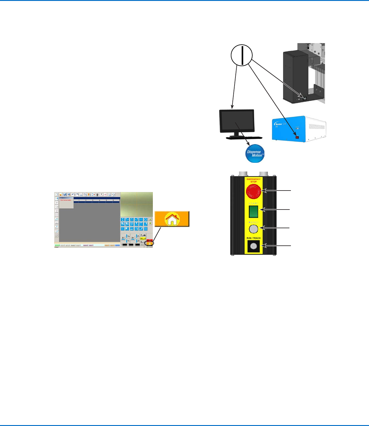
2. Switch on the DispenseMotion controller, monitor, and
GVoperation box.
3. On the start / stop box:
a. Ensure that the EMERGENCY STOP button is not depressed.
b. Turn the RUN / TEACH key to the TEACH position
(recommended for creating a program).
NOTE: When the RUN / TEACH switch is in the TEACH position,
the system will run a dispense cycle, but will not dispense
material.
4. Double-click the DispenseMotion icon to open the dispensing
software.
5. Click HOME.
The robot moves the camera to the home position (0, 0, 0) and the
system is ready.
6. Enable the dispensing system, including the valve controller. Refer to
the dispensing equipment manuals as needed.
7. Refer to the following sections to set up the system and to create
programs for your applications:
• “Concepts” on page26
• “Overview of the DispenseMotion Software” on page29
• “Setup” on page44
• “Programming” on page63
Start / stop box
EMERGENCY STOP
button
START button
RESET button
RUN / TEACH key
GV Series Automated Dispensing Systems
26 www.nordsonefd.com info@nordsonefd.com +1-401-431-7000 Sales and service of Nordson EFD dispensing systems are available worldwide.
Concepts
Before creating any programs, make sure you understand the concepts explained in this section.
About Programs and Commands
A program is a set of commands stored as a file. Each command is stored in the file as a numbered address.
Commands can be subdivided into the following command types:
• A setup command sets a program-level parameter, such as an XYZ coordinate or the Z clearance height.
• A dispense command is tied to an XYZ coordinate and automatically sends a signal to the dispensing system to
execute the dispense command.
When the robot executes a program, it steps through each address in sequence and executes the command
contained in that address. If an address contains a setup command, the system registers that command. If an
address contains a dispense command, the robot moves the X, Y, and Z axes to the location specified for that
command and then performs the dispense command.
Dispense commands are the building blocks of patterns. To program a dispense command, the dispensing tip
is jogged to the desired XYZ location and then a dispense command is registered for that location. This action is
repeated until the desired dispensing pattern is complete. Several examples are provided below.
Setup commands dictate how dispense commands will be executed. Nordson EFD recommends inserting setup
commands at the beginning of a program. The following setup commands are the most commonly used: Backtrack
Setup, Dispense Dot Setup, Dispense End Setup, Line Dispense Setup, Line Speed, and Z Clearance Setup.
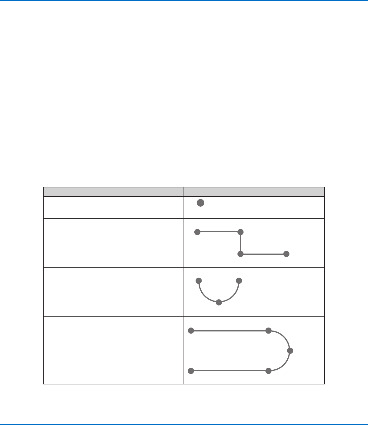
Dispense Command Examples
Commands Resulting Pattern (Overhead View)
To program the robot to dispense a dot of fluid, an XYZ
location is registered as a DISPENSE DOT command.
Dispense Dot
To program the robot to dispense a bead of fluid along
a linear path, the XYZ location of the start of the line is
registered as a LINE START command. The locations
where the tip changes direction are registered as LINE
PASSING commands. The location where the bead of
fluid ends is registered as a LINE END command.
Line Start
Line EndLine Passing
Line Passing
To dispense a bead of fluid in an arc, the XYZ location
of the start of the bead is registered as a LINE START
command. The high point of the arc is registered as an
ARC POINT command. The end of the arc is registered
as a LINE END command.
Arc Point
Line Start
Line End
Lines and arcs can also be combined to dispense a
bead of fluid along a complex path.
Line Start
Line End
Arc Point
Line Passing
Line Passing
GV Series Automated Dispensing Systems
27www.nordsonefd.com info@nordsonefd.com +1-401-431-7000 Sales and service of Nordson EFD dispensing systems are available worldwide.
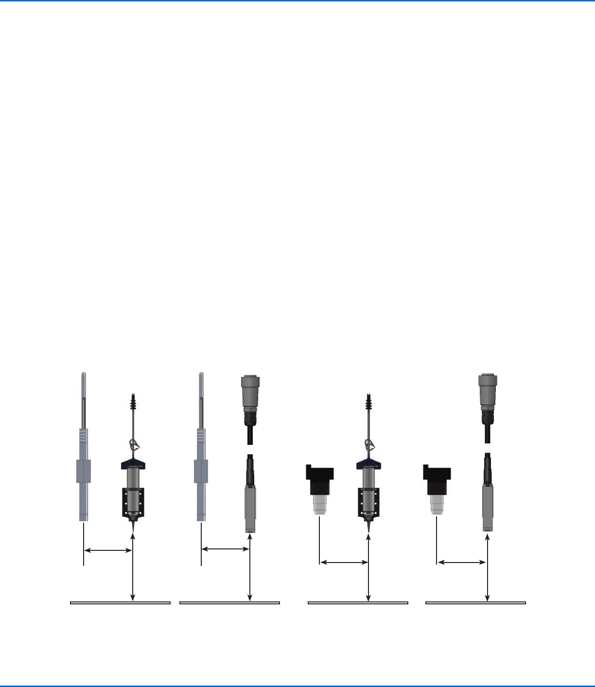
About Offsets
Offset is the distance between two components. The system must be “taught” the following offsets before any
programs are created:
• Camera-to-tip offset: the distance between the center of the camera view and the center of the dispensing tip
(this is an XY offset).
• Tip-to-workpiece offset: (1) the distance between the bottom of the tip and the workpiece for contact
applications or (2) the distance between the bottom of the nozzle and the workpiece for non-contact
applications (this is the Zclearance).
These offsets must be properly calibrated to make sure the dispensing tip follows the same path as the camera and
to compensate for slight variations in height that occur when a dispensing tip or nozzle is changed.
Offsets are taught to the robot during the setup and calibration process, which is guided by the Robot Initial Setup
wizard. This process must be performed for initial startup and also after any change to the system. Examples of
system changes include the following:
• Any time a component installed on the Zaxis (such as the syringe barrel or camera) is moved.
• Any time a dispensing tip or nozzle is changed.
About Programs and Commands (continued)
Best Practices for Programming
• Insert dispense setup commands at the beginning of the program.
• Insert mark commands before any dispense commands.
• Insert dispense commands after inserting setup and mark commands.
• Insert the End Program command at the end of all programs.
Illustration of camera-to-tip offset (also referred to as XY offset) and tip-to-workpiece offset (also referred to as tip height or
Zclearance)
Camera-to-
tip XY offset
Tip-to-
workpiece
offset
(Z clearance)
Tip (nozzle)-
to-workpiece
offset
(Z clearance)
Tip-to-
workpiece
offset
(Z clearance)
Tip (nozzle)-
to-workpiece
offset
(Z clearance)
Camera-to-
tip XY offset
Camera-to-
tip XY offset
Camera-to-
tip XY offset
Pencil
camera
CCD
camera
Syringe
barrel
Jet valve
CCD
camera
Pencil
camera
Syringe
barrel
Jet valve