Nordson_EFD_GV_Series_Operating_Manual - 第44页
GV Series Automated Dispensing Systems 44 www.nordsonefd.com info@nordsonefd.com +1-401-431-7000 Sales and service of Nordson EFD dispensing systems are available worldwide. Setup After installation and before creating a…
GV Series Automated Dispensing Systems
43www.nordsonefd.com info@nordsonefd.com +1-401-431-7000 Sales and service of Nordson EFD dispensing systems are available worldwide.
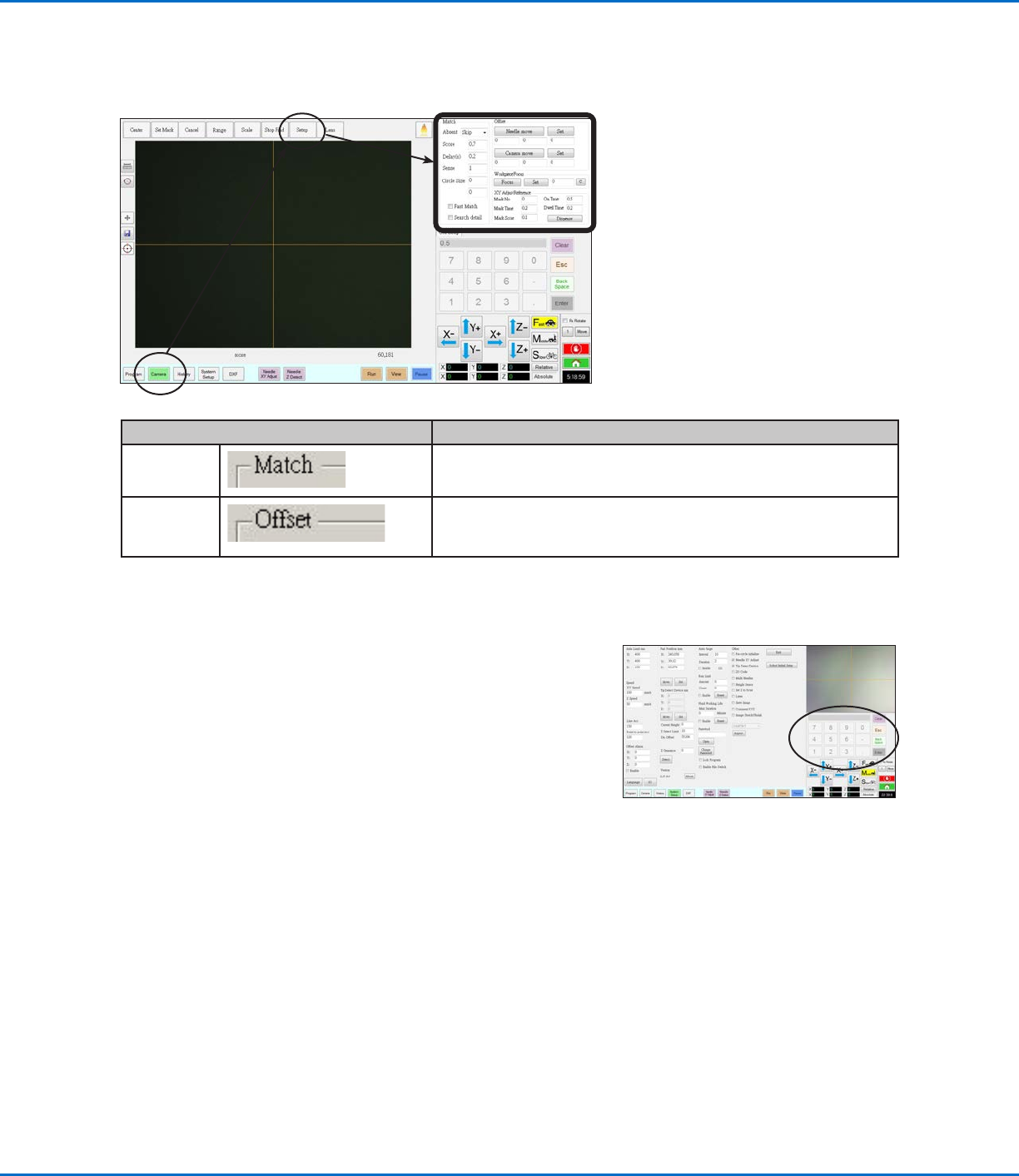
Camera Setup Screen
Click the CAMERA SETUP tab to see the Camera setup fields. The actual view of what the camera sees appears in
the Primary View screen and the camera setup fields appear in the Secondary View screen.
Camera Screen Setup Window Section Function
Match
Affects how the camera searches for marks. Refer to “Setting How
the System Finds Marks (Optional)” on page59.
Offset
Used only as needed for manual calibration of the tip-to-camera
offset in place of using the Robot Initial Setup wizard. Refer to
“AppendixB, Non-Wizard Setup Procedures” on page 124.
Keypad
A numeric keypad appears when data entry fields are present. Use the
keypad for mouse-click entry of numbers as an alternative to using the
numbers on the keyboard. Regardless of how numbers are entered, you
must Enter (on the keypad or the keyboard) for the system to accept the
input.
GV Series Automated Dispensing Systems
44 www.nordsonefd.com info@nordsonefd.com +1-401-431-7000 Sales and service of Nordson EFD dispensing systems are available worldwide.
Setup
After installation and before creating any programs, perform these required and optional setup procedures as
applicable for your automated dispensing system.
System Setup Screen Fields
NOTE: Default values may vary depending on the selected robot model.
Item Screen Capture Description
Axis Limit
Sets the range limits within which the robot can move. A value higher
than the default settings cannot be entered.
Speed
Sets the speed (in mm/s) of the axis movement. For maximum speed
specifications, refer to “Specifications” on page13.
NOTE: You can also change the jog speed settings by clicking the 2 next
to the navigation and jogging window. Refer to “Navigation and Jogging
Window” on page37 for details.
CAUTION
The robot automatically adjusts its speed depending on the complexity
of the pattern. Forcing the robot to run at higher speeds can compromise
accuracy and may disrupt system operation.
Continued on next page
Setting System Parameters
The factory system settings are appropriate for most applications. Use this procedure as needed to view or change
system settings. Important system settings include the following:
• Speed: The speed at which the dispensing tip moves.
• Line Acc: How the robot accelerates from one point to another.
To View or Change System Parameters
#
Click Step Reference Image
1
>
• Click the SYSTEM SETUP tab, then click
OPEN.
2
• View or change parameters as appropriate
for your application. Refer to “System Setup
Screen Fields” below for information on
system-level parameters.
3
• Click another tab to close the System Setup
screen.
NOTE: Settings are automatically saved
except for the Model and Language
selections. Changes to these selections
take effect after you EXIT and reopen the
DispenseMotion software.
GV Series Automated Dispensing Systems
45www.nordsonefd.com info@nordsonefd.com +1-401-431-7000 Sales and service of Nordson EFD dispensing systems are available worldwide.
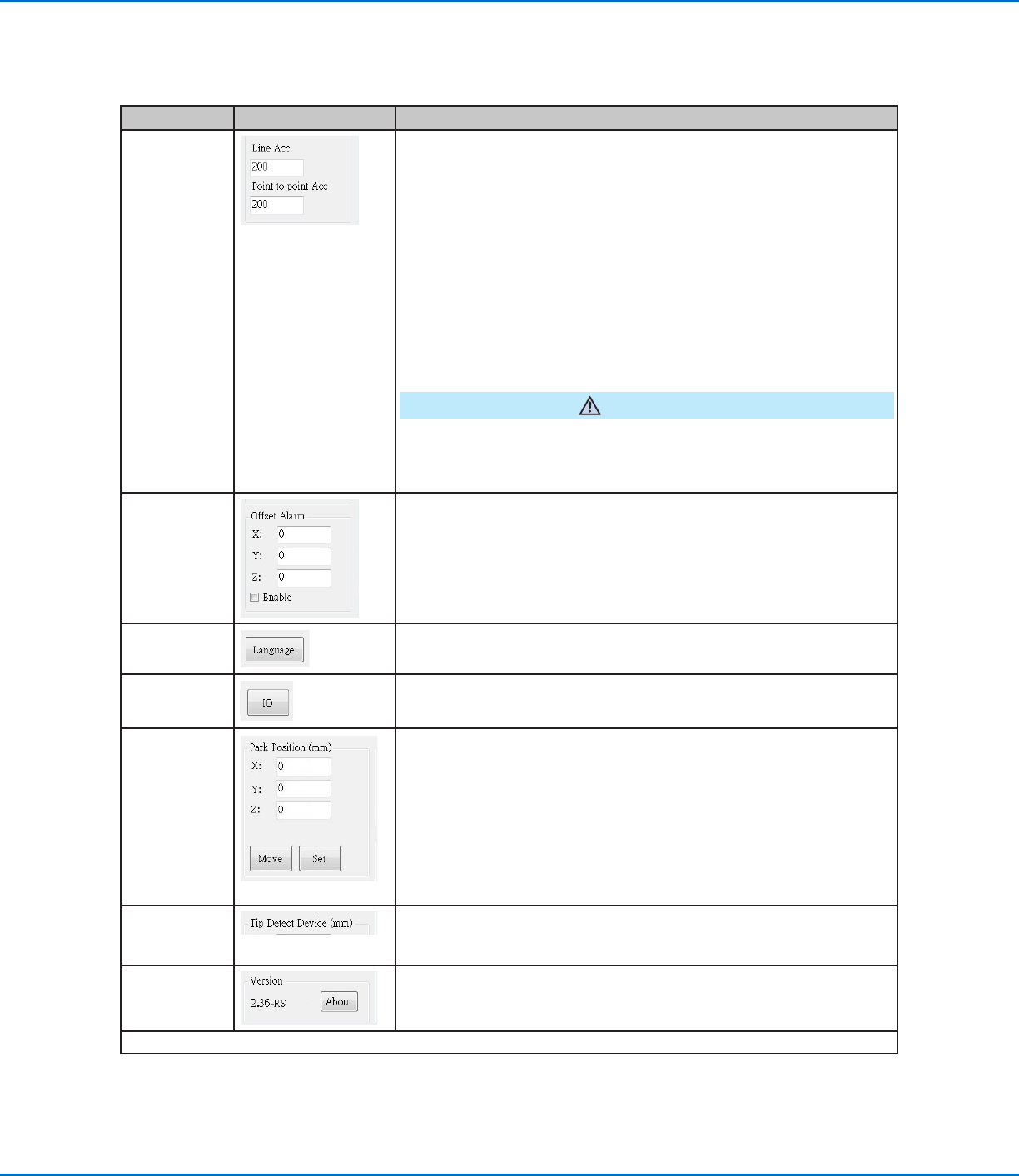
Item Screen Capture Description
Line Acc
Point to point
Acc
Sets the rate of acceleration for line dispensing (Line Acc) or from point
to point (Point to point Acc):
• Line Acc is the dispensing speed within a line command, between
the start- to mid-points, the start- to end-points, and the mid- to
mid-points or mid- to end-points.
• Point to point Acc is the robot movement speed between two
dispense points.
Default: 200 (mm/s
2
)
Range: 20–600 (mm/s
2
)
NOTE: The higher the acceleration, the faster a program runs. However,
higher acceleration settings can also compromise pattern quality.
CAUTION
The robot automatically adjusts its speed depending on the complexity
of the pattern. Forcing the robot to run at higher speeds can compromise
accuracy and may disrupt system operation.
Offset Alarm
Sets how much deviation the system allows for offsets. The default
settings are shown in the screen capture.
EXAMPLE: If Offset Alarm is enabled and the result of an automatic
offset performed by clicking Needle Z Detect or Needle XY Adjust is
outside the XYZ values specified for Offset Alarm, the system displays
an alarm.
Language
Sets the user interface language. Any change takes effect upon system
restart.
IO
Refer to “Setting Up Inputs / Outputs” on page58.
Park Position
Sets the position to which the dispensing tip moves to (1) purge fluid or
(2) when the Park Position command occurs in a program.
Click MOVE to move the tip to the displayed coordinates set for Park
Position. To change the setting, jog the tip to the new location, then click
SET to set the location as the new Park Position.
Tip Detect
Device
Used only as needed for manual calibration of the tip-to-workpiece
offset in place of using the Robot Initial Setup wizard. Refer to
“AppendixB, Non-Wizard Setup Procedures” on page 124.
Version
Shows the current version of the software.
Continued on next page
Setting System Parameters (continued)
System Setup Screen Fields (continued)