Nordson_EFD_GV_Series_Operating_Manual - 第57页
GV Series Automated Dispensing Systems 57 www.nordsonefd.com info@nordsonefd.com +1-401-431-7000 Sales and service of Nordson EFD dispensing systems are available worldwide. How the System Responds to Needle Z Detect or …
GV Series Automated Dispensing Systems
56 www.nordsonefd.com info@nordsonefd.com +1-401-431-7000 Sales and service of Nordson EFD dispensing systems are available worldwide.
Setting Up the System Using the Robot Initial Setup Wizard (continued)
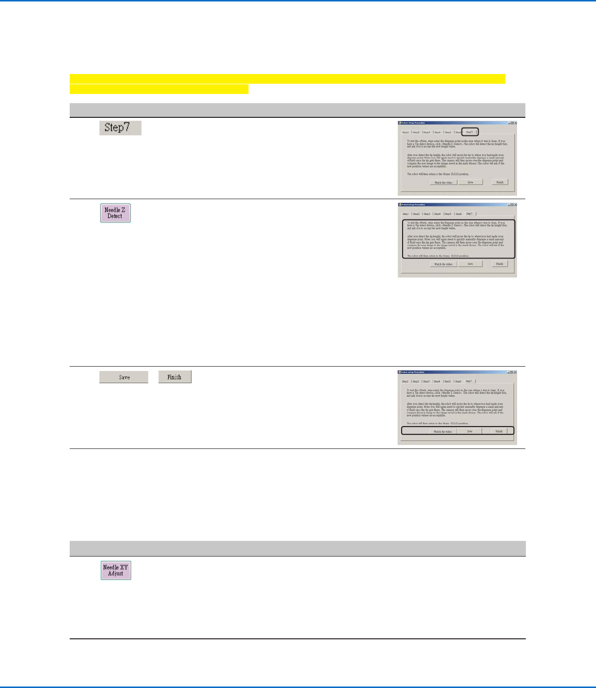
Robot Initial Setup (Step7 Tab): (Only GV Systems With a Tip Detector) Testing the System Setup
and Calibration
Important: If your system does not include a tip detector, skip to “(Only Systems Without a Tip Detector)
Testing the System Setup and Calibration”.
# Click Step Reference Image
1
• Click the STEP7 tab.
2
• Click NEEDLE Z DETECT to test the setup.
• Click YES/OK when prompted for
confirmations.
NOTES:
- When the system performs a Needle Z
Detect, it automatically performs a Needle
XY Adjust directly after performing the
Needle Z Detect.
- Refer to “How the System Responds to
Needle Z Detect or Needle XY Adjust” on
page57 for a detailed description of
the system response to a Needle Z Detect
selection.
3
>
• Click SAVE.
• Click FINISH.
The system is now properly set up and
calibrated. Refer to “Programming” on
page63 to create programs.
(Only Systems Without a Tip Detector) Testing the System Setup and Calibration
#
Click Step
1
SYSTEMS WITHOUT A TIP DETECTOR:
• Click NEEDLE XY ADJUST to test the setup.
• Click YES/OK when prompted for confirmations.
Refer to “How the System Responds to Needle Z Detect or Needle XY
Adjust” on page57 for a detailed description of the system response to a
Needle XY Adjust selection.
The system is now properly set up and calibrated. Refer to “Programming”
on page63 to create programs.
GV Series Automated Dispensing Systems
57www.nordsonefd.com info@nordsonefd.com +1-401-431-7000 Sales and service of Nordson EFD dispensing systems are available worldwide.
How the System Responds to Needle Z Detect or Needle XY Adjust
NOTE: On systems with the optional tip detector, both the Needle XY Adjust and Needle Z Detect buttons are
present. On systems without the optional tip detector, only the Needle XY Adjust button is present.
When you click NEEDLE Z DETECT, the system performs the following actions:
• Moves the dispensing tip over the tip detector sensor and lowers it until it touches the sensor.
• Measures and compares the difference between the last measurement and the current measurement.
• Requests confirmation for any change in the tip-to-workpiece offset (Z clearance).
• Realigns all points in the currently open program to the new tip-to-workpiece offset (Z clearance).
• Automatically performs a Needle XY Adjust sequence (shown below).
When you click NEEDLE XY ADJUST, the system performs the following actions:
• Moves the dispensing tip to a preset location on the workpiece.
• Dispenses a dot of fluid.
• Moves the camera over the deposited dot of fluid.
• Compares the alignment of the dot with the mark image saved in the Mark Library.
• Requests confirmation for any change in the camera-to-tip offset (XY offsets).
• Realigns all points in the currently open program to the new XY offsets.
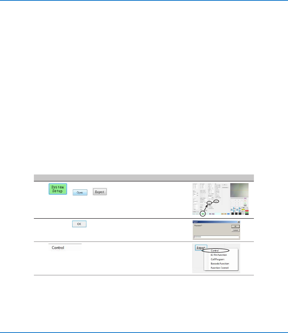
Changing the Robot Model Selection
The correct robot model must be selected for the system to operate properly. Follow this procedure to change the
robot model selection as needed.
# Click Step Reference Image
1
> >
• Click SYSTEM SETUP > OPEN >
EXPERT.
2
11111111 >
• Enter 11111111, then click OK.
3 • Click CONTROL.
Continued on next page
GV Series Automated Dispensing Systems
58 www.nordsonefd.com info@nordsonefd.com +1-401-431-7000 Sales and service of Nordson EFD dispensing systems are available worldwide.
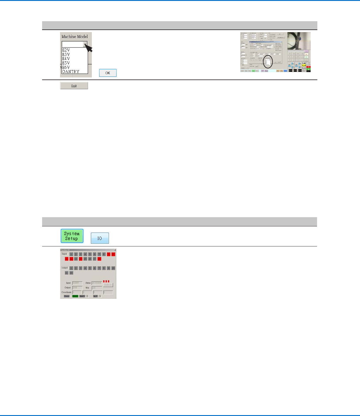
Setting Up Inputs / Outputs
If you connected inputs / outputs, follow this procedure to test input / output connections.
NOTE: All automated dispensing systems provide 8 standard inputs and 8 standard outputs. A kit to expand to
16inputs and 16 outputs is available. Refer to “Accessories” on page89.
PREREQUISITES
The system is properly installed and set up. Refer to “Installation” on page19 and “Setup” on page44.
Input / output wiring is properly connected. Refer to “I/O Port” on page95 for wiring diagrams.
#
Click Step
1
>
• Click SYSTEM SETUP > IO.
2
• Click the outputs you want turn ON or OFF, then click the X to close the
window.
NOTES:
• Inputs flash red when they are turned ON.
• Use only inputs / outputs 1 through 8. The remaining I/Os are reserved for the
system.
Configuring Input / Outputs for a Special Purpose
The IO Pin Function feature provides a set of user-configurable conditions that affect the operation of the robot.
Refer to “AppendixG, I/O Pin Function Setup” on page146.
Changing the Robot Model Selection (continued)
# Click Step Reference Image
4
>
• Select the correct robot model from
the Machine Model drop-down menu.
• Click OK to save.
5
• Click EXIT to close the software.
• Switch off the robot.
• Re-open the DispenseMotion
software and switch on the robot for
the change to take effect.