Nordson_EFD_GV_Series_Operating_Manual - 第94页
GV Series Automated Dispensing Systems 94 www.nordsonefd.com info@nordsonefd.com +1-401-431-7000 Sales and service of Nordson EFD dispensing systems are available worldwide. 2 1 3 1 7 Maximum V oltage Maximum Current 125…
GV Series Automated Dispensing Systems
93www.nordsonefd.com info@nordsonefd.com +1-401-431-7000 Sales and service of Nordson EFD dispensing systems are available worldwide.
Technical Data
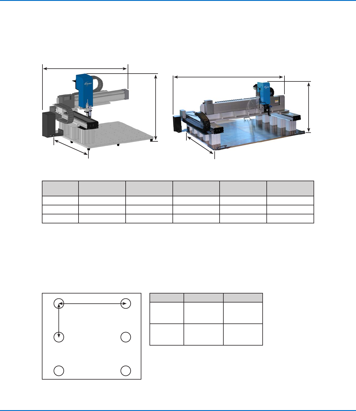
Dimensions
Dimension
G4V
100 mm post
G4V
150 mm post
G4V
250 mm post
G8V
100 mm post
G8V
150 mm post
A (width) 937 mm (37") 937 mm (37") 937 mm (37") 1,581 mm (62") 1,581 mm (62")
B (height) 561 mm (22") 611 mm (24") 711 mm (28") 650 mm (26") 700 mm (28")
C (depth) 760 mm (30") 760 mm (30") 760 mm (30") 1,190 mm (47") 1,190 mm (47")
NOTE: These dimensions include the DispenseMotion controller, fixture plate, and posts.
Robot Feet Mounting Hole Template
Use these dimensions to drill mounting holes for the robot feet.
6 x M5 tapped holes
Dimension G4V G8V
A
(Center to
center)
709mm
(28")
n/a
B
(Center to
center)
326mm
(13")
n/a
G4V
A
G8V
B
C
B
A
B
C
A
GV Series Automated Dispensing Systems
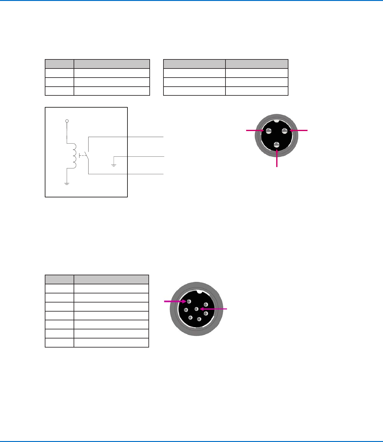
94 www.nordsonefd.com info@nordsonefd.com +1-401-431-7000 Sales and service of Nordson EFD dispensing systems are available worldwide.
2
1 3
1
7
Maximum Voltage Maximum Current
125 VAC 15A
250 VAC 10A
28 VDC 8A
Pin# Description
1 NOM (Normally open)
2 COM (Common)
3 EARTH (Ground)
Pin 1
Pin 2
Pin 3
+24V
Relay
Ext. Control Port
NOTES:
• Inputs are not polarity-sensitive.
• The optional start / stop box accessory facilitates input / output connections to this port. Refer to “Start / Stop
Box” on page90 for part numbers.
Pin Description
1 Ground
2 Start signal
3 Motor power
4 Motion idle
5 Run / Teach
6 Emergency stop
7 Emergency stop
Technical Data (continued)
Wiring Diagrams
Dispenser Port
GV Series Automated Dispensing Systems
95www.nordsonefd.com info@nordsonefd.com +1-401-431-7000 Sales and service of Nordson EFD dispensing systems are available worldwide.
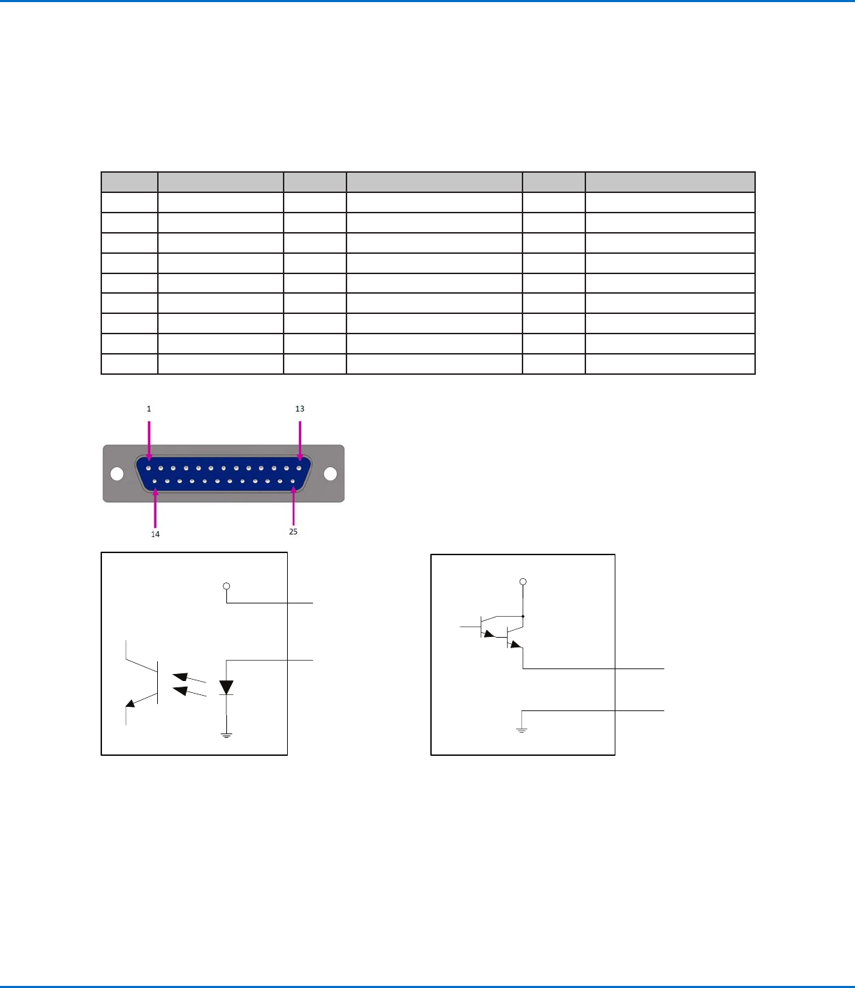
I/O Port
NOTES:
• Outputs are rated at 125 mA.
• Courtesy +24 VDC output is rated at 3.0 Amp.
Pin Description Pin Description Pin Description
1 Input 1 10 Not connected 19 Output 6
2 Input 2 11 GND 20 Output 7
3 Input 3 12 GND 21 Output 8
4 Input 4 13 GND 22 Not connected
5 Input 5 14 Output 1 23 Not connected
6 Input 6 15 Output 2 24 +24 VDC
7 Input 7 16 Output 3 25 +24 VDC
8 Input 8 17 Output 4
9 Not connected 18 Output 5
Technical Data (continued)
Input schematic Output schematic
Pin 25
Input X
+24V
Output X
Pin 13
+24V