00198168-02_Technical_Training_TX-Series_EN.pdf - 第103页
5 Placement Heads 5.2 C&P20 P/M2 Head Technical Training SIPLACE TX-Series 10/2016 103
5 Placement Heads
5.2 C&P20 P/M2 Head
102 Technical Training SIPLACE TX-Series 10/2016
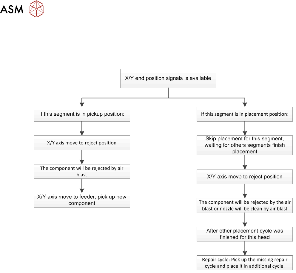
Placement Procedure
"High force": Placement force depends on current of Z Axis, to determine end signal of Z Axis down
and vacuum generator switch to air blast.
Reject Procedure
"Defective" or "missing" is determined by:
●
Optical centering
●
Component sensor
Temperature Compensation
The temperature sensor is regularly checked and offset value will be calculated and will be used to
increase placement accuracy.

5 Placement Heads
5.2 C&P20 P/M2 Head
Technical Training SIPLACE TX-Series 10/2016 103
5 Placement Heads
5.2 C&P20 P/M2 Head
104 Technical Training SIPLACE TX-Series 10/2016
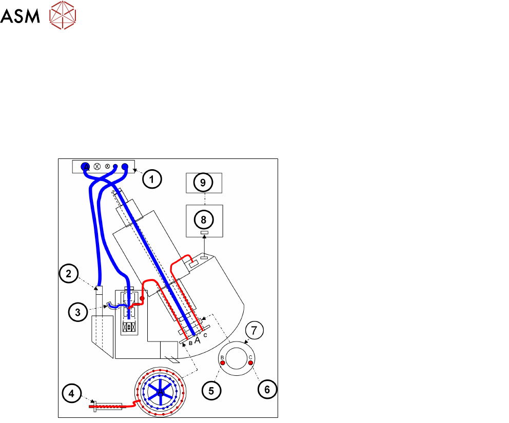
5.2.4 Vacuum System Overview
5.2.4.1 Vacuum System Function Overview
The vacuum system consists of two main parts:
Pickup/placement circuit: vacuum to pickup and hold the component, air kiss for placement.
Holding circuit: holding the component when component is on nozzle but not in pickup position.
Pickup Circuit (Vacuum)
1. Vacuum distributor (4.8 -5.0 bar)
2. Z Axis retract unit
3. Air for cooling system X Motor
4. Segment
5. Pickup/placement circuit
6. Holding circuit
7. Smoothed distributor disc
8. Intermediate distributor board
9. MHCU
●
During the pickup process, maximum vacuum is applied to the nozzle.
●
Measurement of vacuum/ air kiss value is performed by the pressure control valve.
Placement/Reject Circuit (Air Kiss)
●
The pickup/placement circuit is connected to the hold circuit via the smoothed distributor disc.
●
The PRV valve can be infinitely adjusted between max. Vacuum and max. air kiss in the
pickup/placement circuit.