00198168-02_Technical_Training_TX-Series_EN.pdf - 第109页
5 Placement Heads 5.2 C&P20 P/M2 Head Technical Training SIPLACE TX-Series 10/2016 109 5.2.5.1 CAN Bus Overview
5 Placement Heads
5.2 C&P20 P/M2 Head
108 Technical Training SIPLACE TX-Series 10/2016
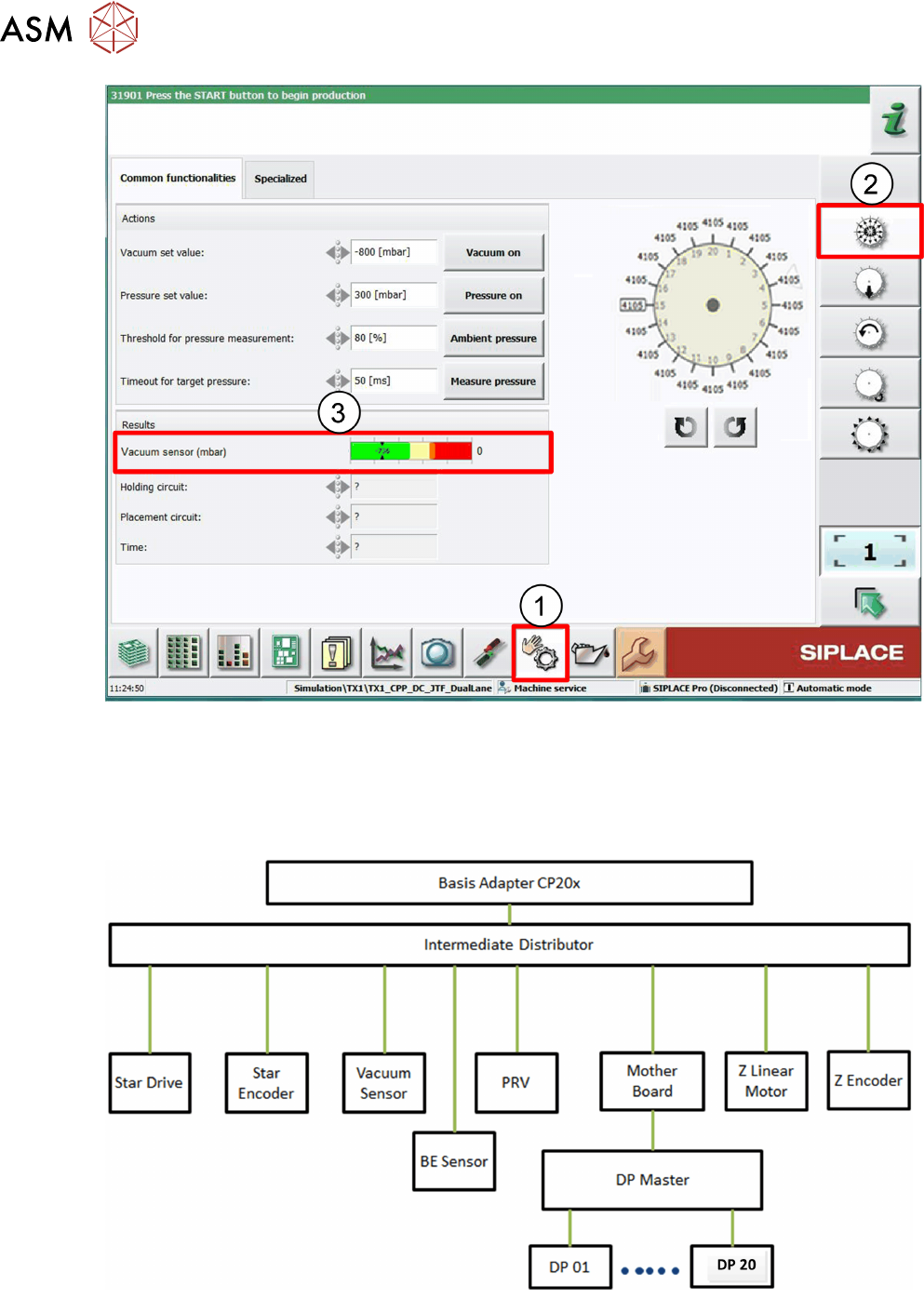
1. Click on Check sensor and functions menu.
2. Click on Check vacuum functions menu.
3. In the Vacuum senor field the current vacuum values are displayed.
5.2.5 Power Control and Communication
5 Placement Heads
5.2 C&P20 P/M2 Head
Technical Training SIPLACE TX-Series 10/2016 109
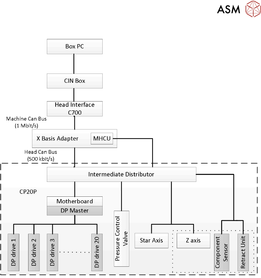
5.2.5.1 CAN Bus Overview
5 Placement Heads
5.2 C&P20 P/M2 Head
110 Technical Training SIPLACE TX-Series 10/2016
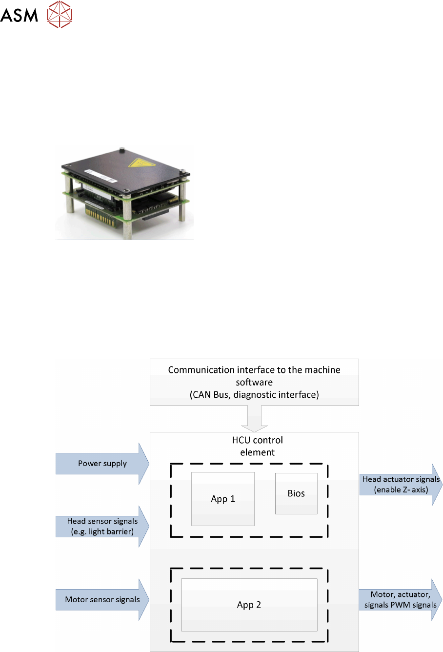
5.2.5.2 MHCU General
The task of the MHCU is the position control of the head axis (C&P20, CPP und Twin Head).
Further the MHCU integrates the functions of the PRV, the component sensor and the
communication interface for the DP Axis.
The unit consists of a control module (CM) and a power module (PM) comparable to the axis card
as control module and the servo card as power module.
MHCU Function Power Supply
●
The power supply delivers 42V for the electronic and Z Axis.
●
The power cube on the head interface (C700) supplies the MHCU with 25V.
●
All required internal voltages (+24V, +15V, -15V, +5V, +3.3V, +1.5V) are generated by the
head interface at the gantry.
●
In addition, the operating voltages for the axes (150 V for star / 42V for Z-) are supplied by
MGCU.
MHCU Function
The head control unit is responsible for central control, adjustment of the axis and for communica-
tion with the computer system via CAN bus.
Tasks of the software application:
●
BIOS is responsible for the booting of the MHCU (Tri-core)
●
Application 1: communication with machine software
●
Application 2: motor control