00198168-02_Technical_Training_TX-Series_EN.pdf - 第114页
5 Placement Heads 5.2 C&P20 P/M2 Head 114 Technical Training SIPLACE TX-Series 10/2016 Connectors X1, X2 Flat ribbon cable to the head adapter X3 Power supply for star motor X8 Power supply for Z Axis X15 Valve for r…
5 Placement Heads
5.2 C&P20 P/M2 Head
Technical Training SIPLACE TX-Series 10/2016 113
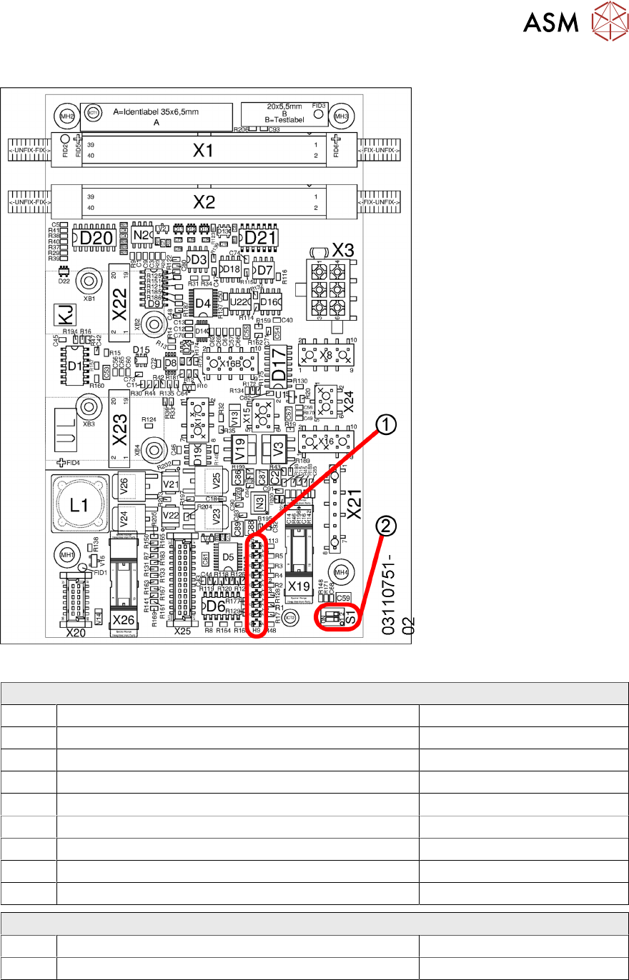
5.2.6.2 Intermediate Distributor Board LEDs
1. LEDs
2. DIP-Switches
Note:
Depending on the head, the
PCB has a different part
number.
LEDs
H1 Fan Yellow
H2 Fan error Red
H5 + 5V Green
H6 + 15V Green
H8 + 24V Green
H9 Error 24 V DP Red
H11 24 V DP ON Yellow
H12 Return cylinder ON Yellow
H13 Pressure control valve status Yellow
DIP Switches
S1 DP Power ON 1-4 Off
S2 Z down test 2-3 OFF

5 Placement Heads
5.2 C&P20 P/M2 Head
114 Technical Training SIPLACE TX-Series 10/2016
Connectors
X1, X2 Flat ribbon cable to the head adapter X3 Power supply for star motor
X8 Power supply for Z Axis X15 Valve for return unit
X16 CAN bus X16b CAN bus
X17 Z Axis light barrier down X19 Board for holding circuit vacuum sensor
X20 Power supply for ED distributor X21 Diagnosis connector
X22 Incremental star X23 Incremental Z Axis
X24 Fan X25 Digital pressure control valve
X26 Component sensor
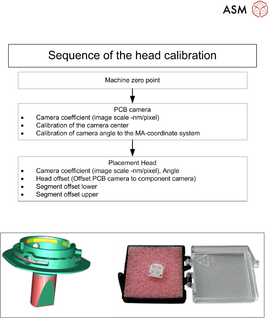
5.2.7 Calibration
5.2.7.1 Calibration
Calibration - Overview Description
This calibration step first measures the component camera. This determines the relationship of
"camera pixel size to resolution of machine measuring system (X, Y)", the "camera center point in
X/Y direction" and the "torsion angle of the CCD sensor in the camera". This is following by
determining the head offset and the segment offsets for the top and bottom.
●
Head offset: the head offset is the distance between the PCB camera and the nozzle
(segment1). The target is a fixed value, to which an offset value (from the head calibration) is
added.
TX micron only: During the placement cycle the head offset is periodically checked and
calibrated.
●
Segment offset top: the top segment offset involves turning the calibration tool in the
component camera in 0°, 90°, 180° and 270° steps. The value determined is that of the
rotating center of the nozzle tip in relation to the component camera center in the X/Y
direction.
●
Segment offset bottom: the bottom segment offset involves recording and measuring the
calibration tool in the 0°, 90°, 180° and 270° positions. The value determined is that of the
rotating center point of the nozzle tip when the Z Axis is extended in relation to the PCB
camera. segment1 forms the reference (X=0, Y=0) to the other segments.
5 Placement Heads
5.2 C&P20 P/M2 Head
Technical Training SIPLACE TX-Series 10/2016 115
Calibration – Procedure
For calibrating the C&P20 P and the C&P20 M2 head the calibration tool [03034148-xx] and nozzle
4235 [03098748-xx] have to be used.