00198168-02_Technical_Training_TX-Series_EN.pdf - 第131页
5 Placement Heads 5.3 Twin Head Technical Training SIPLACE TX-Series 10/2016 131 5.3.1.2 Technical Data Component spectrum Camera Component Range Camera 33:0402 to SO, PLCC, QFP, BGA, special components, bare dies, flip-…
5 Placement Heads
5.3 Twin Head
130 Technical Training SIPLACE TX-Series 10/2016
5.3 Twin Head
5.3.1 Overview
5.3.1.1 Overview
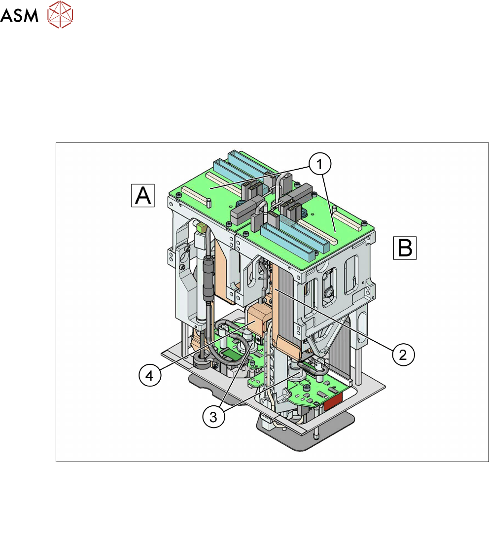
The Twin Head consists of two identical modules which work according to the Pick & Place
principle. The second P&P segment is rotated 180 degrees.
A – Modul 1
B – Modul 2 (rotated 180° compared to module 1)
1. Main board on module 1 and module 2
2. Linear motor / ZAxis
3. D Axis
4. Incremental measurement system /
ZAxis
5 Placement Heads
5.3 Twin Head
Technical Training SIPLACE TX-Series 10/2016 131
5.3.1.2 Technical Data
Component spectrum Camera
Component Range Camera 33:0402 to SO, PLCC, QFP, BGA,
special components, bare dies, flip-chips
Camera 25: 0201 to SO, PLCC, QFP, sockets,
plugs, BGA, special components, baredies,
flip-chips, shields
Placement accuracy (X/Y) Camera 33: ± 28 μm/3σ
Camera 25: ± 22 μm/3σ
Placement accuracy (Angle) Camera 33 ± 0.05° / 3σ
Camera 25: ± 0.05° / 3σ
Maximum component size: Camera 33: 55 mm x 45 mm (single
measurement) or 75 mm x 10 mm (multiple
measurement)
Camera 25: 16 mm x 16 mm (single
measurement)
Max. component height 25 mm
Programmable placement force 1 - 15 N
Nozzle types 5xx (4xx, 8xx, 9xx with adapter) Gripper
Distance between the segments approx. 71,00 mm
Max. weight of component 100 g
For full specification refer to the user manual.
Twin Head Types:
The following types of P&P Heads are available:
●
Twin Head (2 segments, 15 Nm)
●
VHF P&P
●
Twin HF (2 Segments, 30 Nm)
●
Twin VHF (2 Segments, 70 Nm, 40mm)
The different placement heads can be used on the following machines types*:
Machine Twin Head Twin HF VHF P&P Twin VHF
X-Series X X
SX1 SX2 DX1
DX2
X X
SX1 V2, SX2 V2 X X X X
SX4/DX4 X X
X2 S X X
X3 S/X4 S X X
TX-Series* X
*Twin Heads are not available for TX micron.
5 Placement Heads
5.3 Twin Head
132 Technical Training SIPLACE TX-Series 10/2016
5.3.1.3 Main Parts / Unit Overview
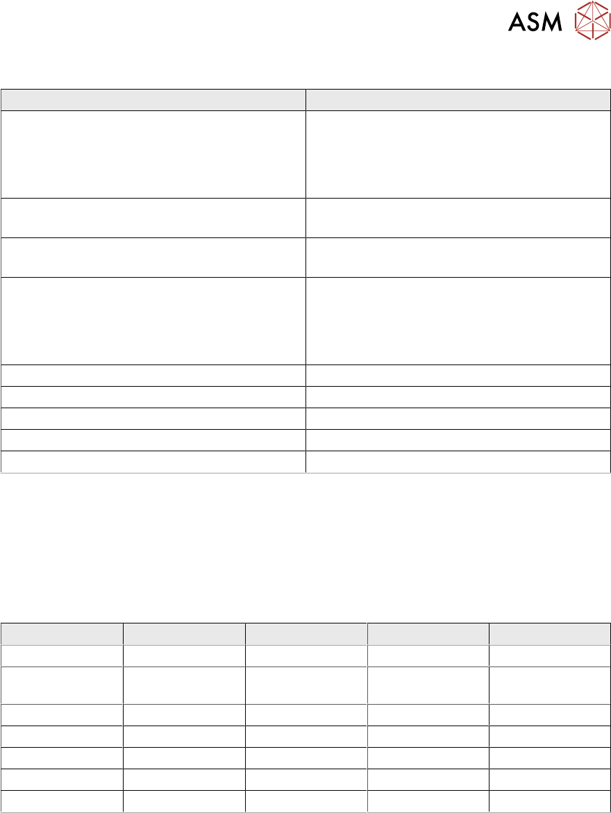
Twin Head – Pressure Regulator Valve (PRV)
1. Compressed air connection
2. Output vacuum is passed through the D
Axis motor shaft and on to the nozzle
3. Discharged air for cooling the X linear
motor
The PRV automatically controls the vacuum, air blast and the zero balancing position (middle
position-→ no vacuum and no air blast) for the segments.
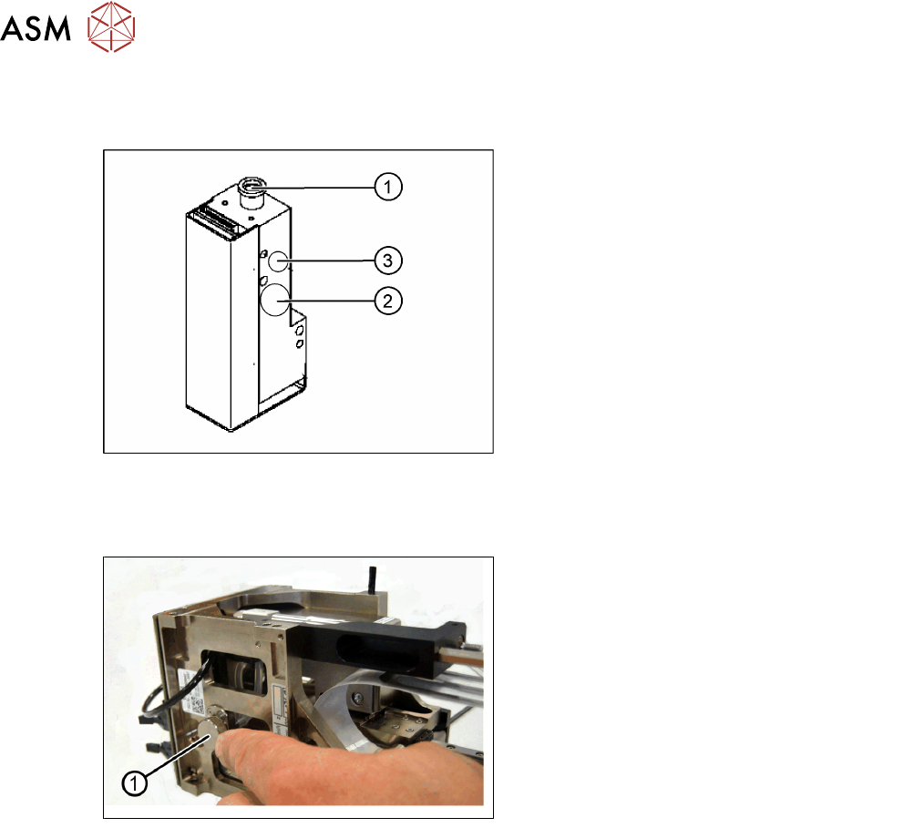
Twin Head – Filter
1. Filter for the vacuum system.
The Filter is mounted on the return unit and
used as an attenuator to control the vacuum.
The filter with the additional volume reduces the oscillation of the vacuum generator and
guarantees an accurate vacuum and air blast supply.
The filter is serviced at regular intervals, which must be adhered to (see maintenance Job Card).