00198168-02_Technical_Training_TX-Series_EN.pdf - 第134页
5 Placement Heads 5.3 Twin Head 134 Technical Training SIPLACE TX-Series 10/2016 Reference Run: Vacuum Check After the processor for the PRV has booted, the PRV is initialized. This means that neither vacuum nor air blas…
5 Placement Heads
5.3 Twin Head
Technical Training SIPLACE TX-Series 10/2016 133
5.3.2 Reference Run
The Twin Head consists of two segments which have two axes Z and D and the X and Y Axes at
the gantry.
Before reference run the return cylinder is moved out to the lower home position. On both modules
the vacuum is on until the PRV is initialized.
The Twin Head reference run is performed parallel to the C&P Heads reference run.
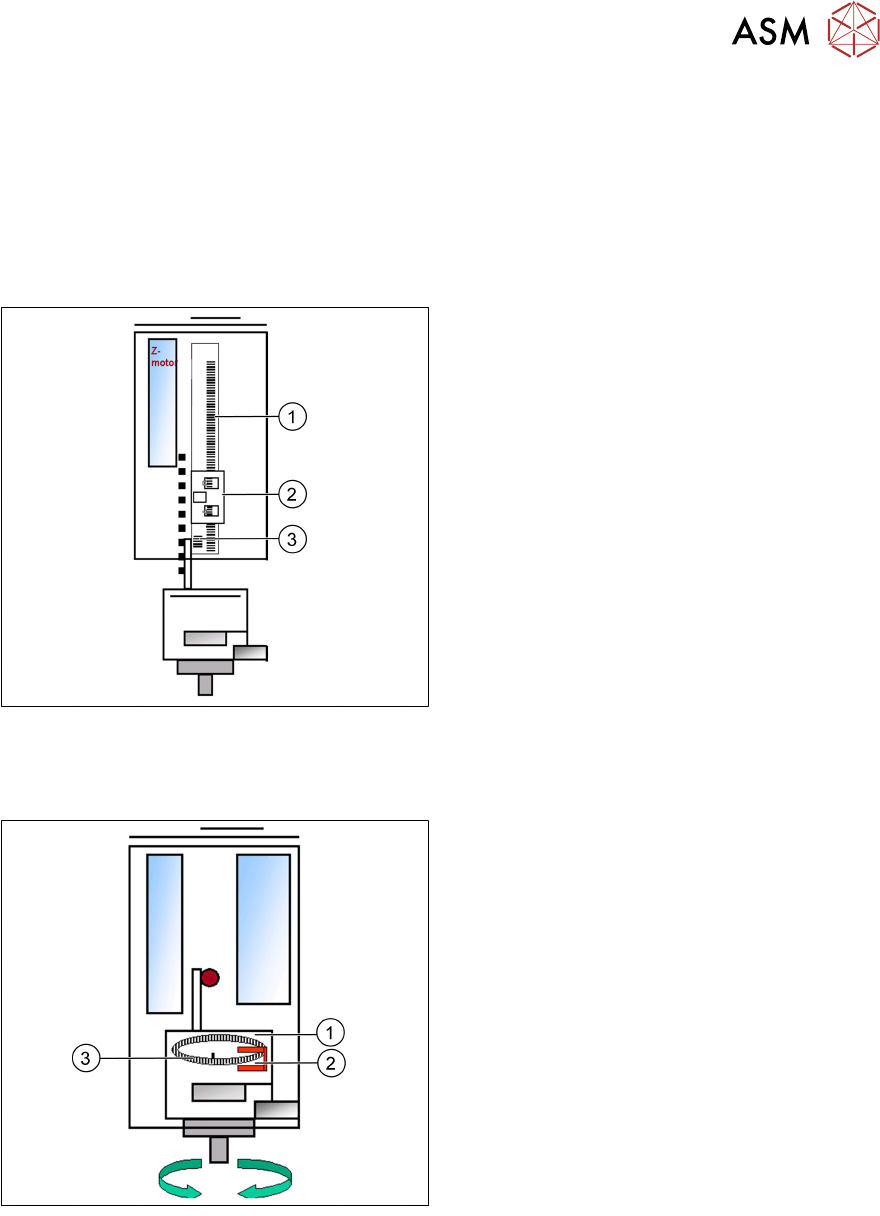
Reference Run: Z Axis
1. Incremental scale mounted on moveable
part of the Z Axis
2. Fixed Incremental encoder
3. Zero pulse on the incremental scale
●
Z Axis search for the commutation point of
the linear motors (special mode due risk of
a movement downwards).
●
Then the Z Axis move upwards to the Zero
pulse and load the zero point correction.
●
Then the Z Axis move upwards to the Zero
pulse and load the zero point correction.
The zero point correction, max. and min. travel range are determined when you calibrate the head
height.
Reference Run: DP Axis
1. Incremental glass scale D Axis
2. Incremental encoder
3. Zero pulse on the incremental glass scale
●
The D Axis runs to the zero pulse of the D
Axis encoder.
●
The zero point correction value will be
loaded.
●
The D Axis moves to the reference
position.
5 Placement Heads
5.3 Twin Head
134 Technical Training SIPLACE TX-Series 10/2016
Reference Run: Vacuum Check
After the processor for the PRV has booted, the
PRV is initialized. This means that neither
vacuum nor air blast is generated at the nozzle.
Note: The “closed” vacuum value for the Twin
segments relates to the calibration value.
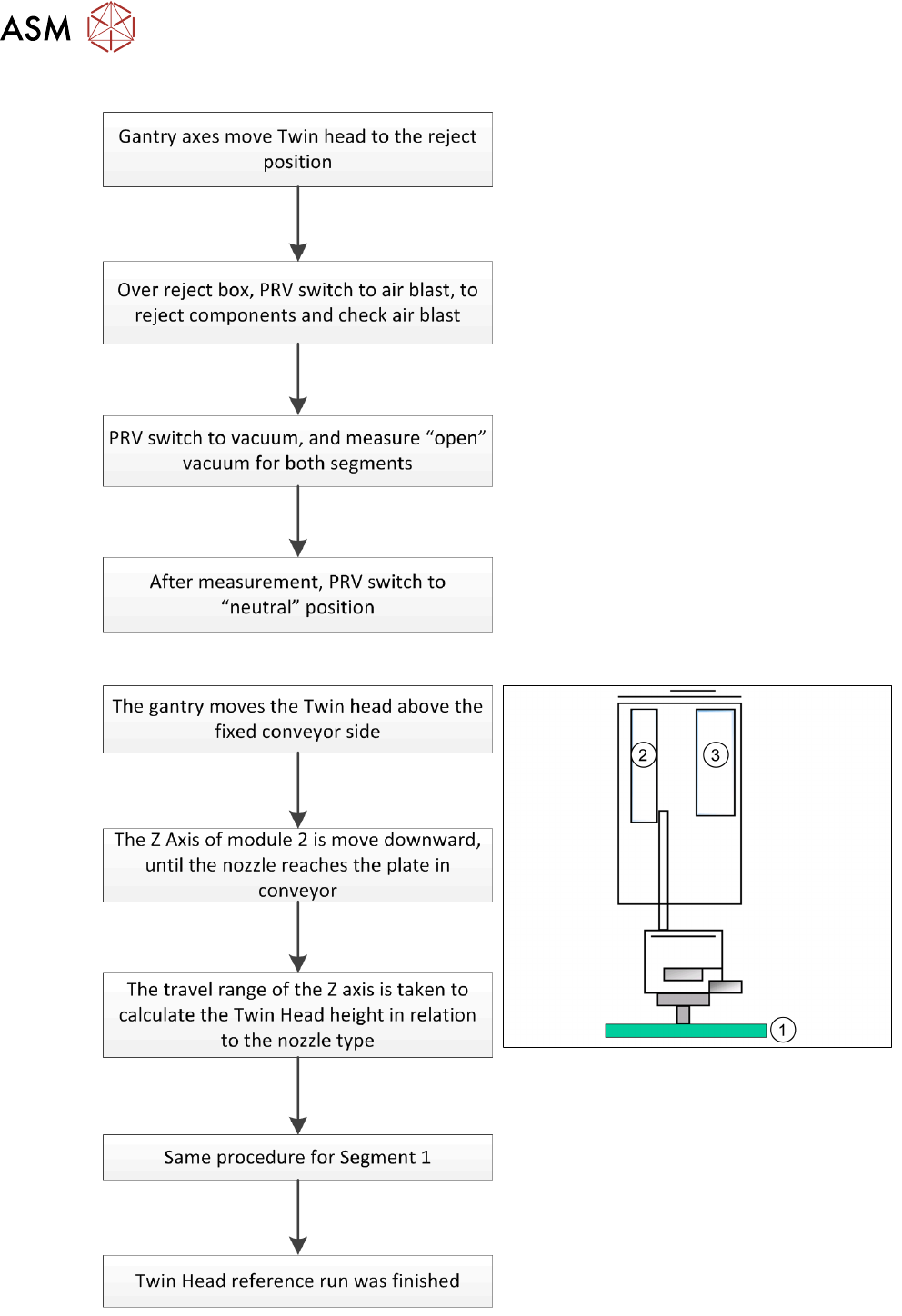
Reference Run: Height Of Nozzle
1. Top of fixed conveyor side
2. Z Motor
3. Vacuum - air blast distribution
With this function we check that the
programmed nozzle type is on the segment.
The nozzle length is taken to calculate the pick
up and placement height for the following
placements.
5 Placement Heads
5.3 Twin Head
Technical Training SIPLACE TX-Series 10/2016 135
Reference Run: Vacuum Value Explanation
After the CAN bus processor for the vacuum/air blast distributor has booted, the vacuum / air blast
distributor is initialized. This means that vacuum/air blast generator is adjusted to ensure that
neither vacuum nor air blast is generated at the nozzle.
The gantry axes move the Twin Head to the reject position.
●
Over the reject box the vacuum / air blast generator switches to air blast to reject components
and check the air blast.
●
The vacuum/air blast generator now switches over to vacuum and the open vacuum at the
segments is measured*.
●
After measurement, the pressure is adjusted back to 0 bar
●
The vacuum reference run has now been completed for the Twin Head.
*The closed vacuum value for the Twin segments relates to the calibration value.
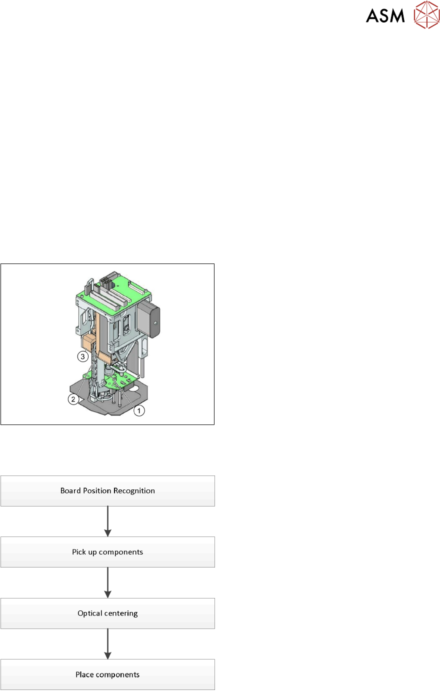
5.3.3 Placement Process
Twin Head - Working Position
1. DP Axis
2. Z Axis drive
3. Incremental distance measuring system for
the Z Axis
All following procedures are for both Segments.
Twin Head - Placement Workflow
●
PCB camera centers fiducials after PCB is
clamped to determine the exact position of
the board in the machine.
●
Max. 2 components will be pick up from
feeder (1-per segment).
●
These components will be centered by
IC-camera and prepared for placement.
●
Place components on PCB.