00198168-02_Technical_Training_TX-Series_EN.pdf - 第139页
5 Placement Heads 5.3 Twin Head Technical Training SIPLACE TX-Series 10/2016 139 5.3.4 Vacuum System Overview 5.3.4.1 Vacuum System A - Piston in "open" position B - Piston in "closed" position 1. Ven…
5 Placement Heads
5.3 Twin Head
138 Technical Training SIPLACE TX-Series 10/2016
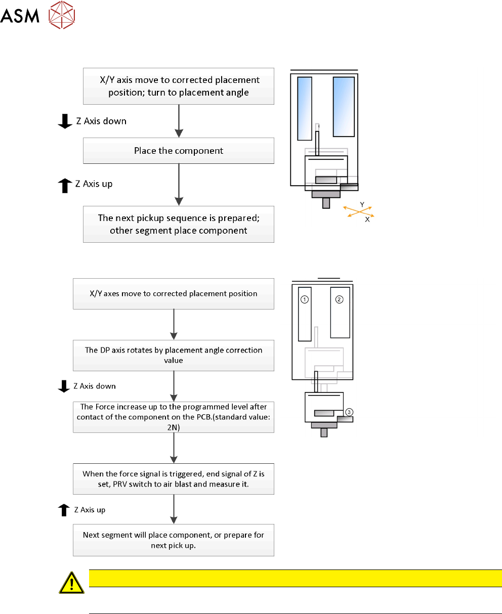
Twin Head - Placement Workflow
Standard Placement Detailed
1. Z motor
2. PRV to switch vacuum or air blast
3. Force sensor: measure contact force
CAUTION
If the air blast pressure is not reached during placement, a vacuum check will be performed
in the Z Axis up position to see whether the component has been placed or not.
Temperature compensation
The temperature sensor is regularly checked and offset value will be calculate and will be used to
increase placement accuracy.
5 Placement Heads
5.3 Twin Head
Technical Training SIPLACE TX-Series 10/2016 139
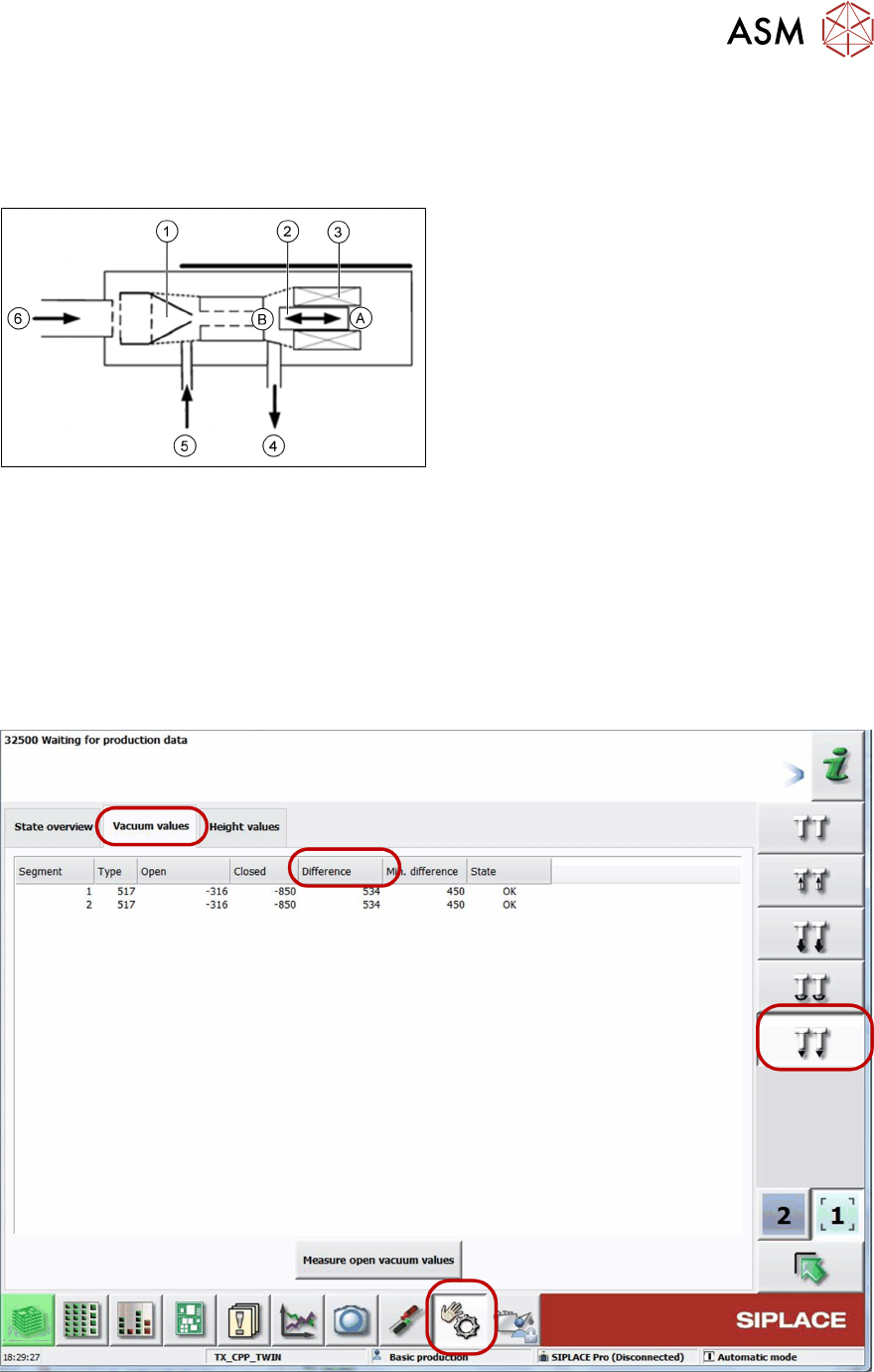
5.3.4 Vacuum System Overview
5.3.4.1 Vacuum System
A - Piston in "open" position
B - Piston in "closed" position
1. Venturi nozzle
2. Plunger (iron core)/ piston
3. Plunger drive (inductor)/ driver circuit
4. Discharged air to silencer
5. Vacuum or air kiss output
6. Compressed air input
PRV – function
●
During pickup the piston is always in the “open” position, in which maximum vacuum is
applied to the nozzle.
●
During placement, the piston is in the "close" position, air kiss is produced and applied to
nozzle for placement.
●
In the placement cycle the time to switch between maximum vacuum (-850 mbar) to
maximum air kiss (+400 mbar) is < 12ms.
5.3.4.2 Station Software Vacuum Check
●
In the case of vacuum errors the vacuum system can be tested using the station software.
●
The differences between open and closed values are measured as reference value for nozzle
check.
5 Placement Heads
5.3 Twin Head
140 Technical Training SIPLACE TX-Series 10/2016
5.3.5 Handling
Twin Head – Lowering the Z Axis
Manual Lowering of Z Axis
The Twin Head is designed for a placement force of 1.0 to 15N.
The Z Axis needs to be very smooth-running, especially for low placement forces. Therefore, the
ZAxis has to be handled carefully.
Cause of Hazard
When manually lowering the Z Axis, the Twin Head module can be easily damaged!
●
Manual lowering may only be done.
Before performing manual lowering of the Z Axis, make sure the Z Axis has been released.
●
When releasing the ZAxis, the ZAxis return cylinder moves upwards.
●
If the axis is not released, the return cylinder will automatically move upwards when the ZAxis
is manually lowered, which could cause injuries and damage to the placement head.
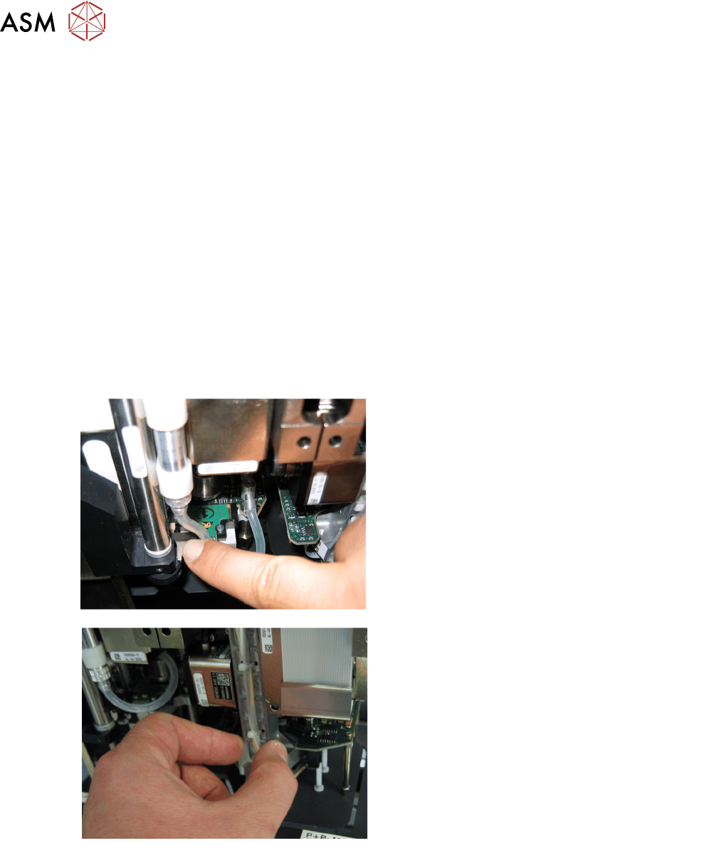
Lowering the Z Axis
Lowering the ZAxis at P&P Module1
To safely press the ZAxis downwards, apply
manual pressure to the marked part of the retract
unit driver.
Lowering the ZAxis at P&P Module2
The ZAxis can be moved downwards at segment
2 by taking hold of the carrier arm from both
sides and then pushing this down.