00198168-02_Technical_Training_TX-Series_EN.pdf - 第140页
5 Placement Heads 5.3 Twin Head 140 Technical Training SIPLACE TX-Series 10/2016 5.3.5 Handling Twin Head – Lowering the Z Axis Manual Lowering of Z Axis The Twin Head is designed for a placement force of 1.0 to 15N. Th…
5 Placement Heads
5.3 Twin Head
Technical Training SIPLACE TX-Series 10/2016 139
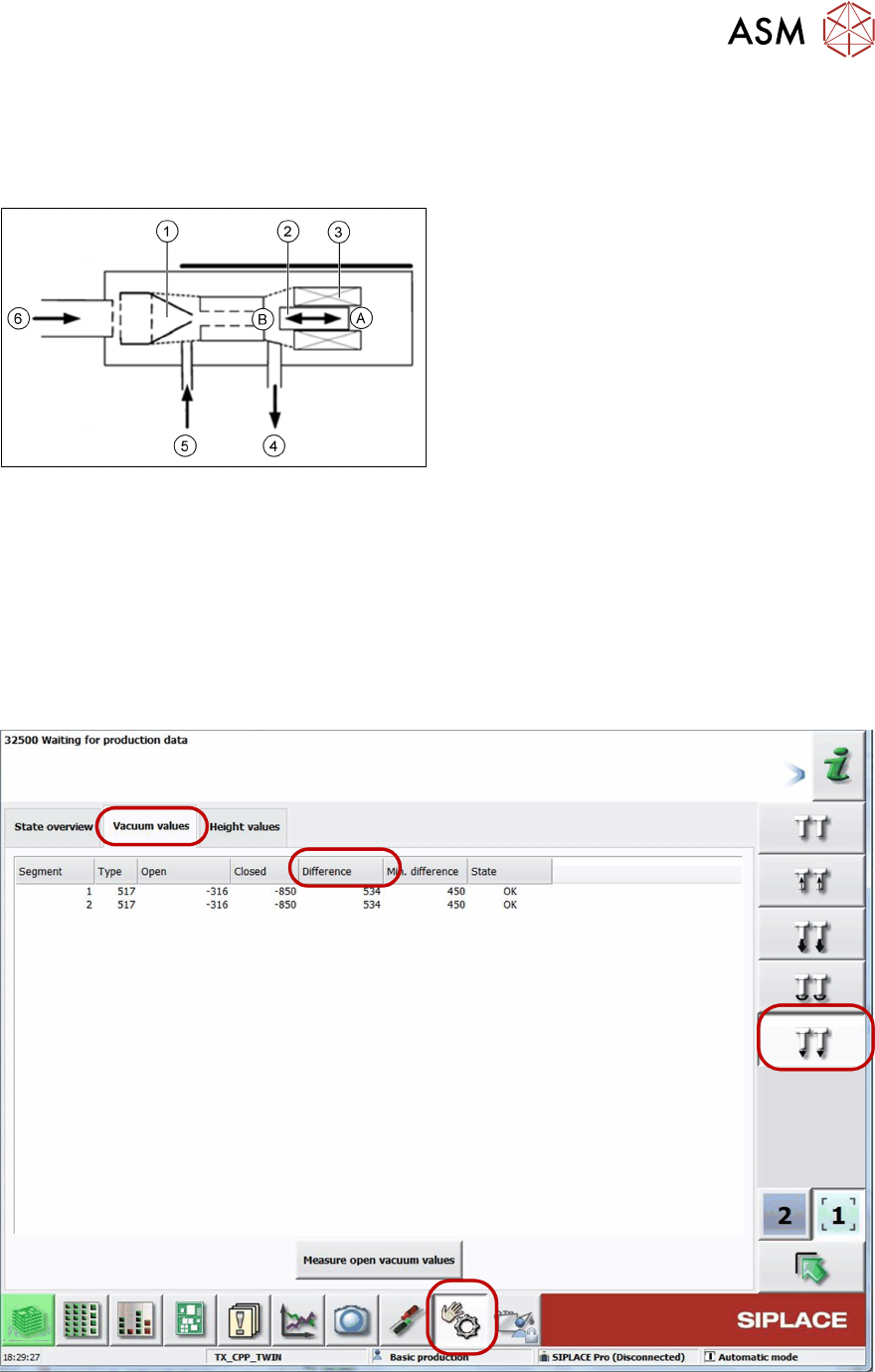
5.3.4 Vacuum System Overview
5.3.4.1 Vacuum System
A - Piston in "open" position
B - Piston in "closed" position
1. Venturi nozzle
2. Plunger (iron core)/ piston
3. Plunger drive (inductor)/ driver circuit
4. Discharged air to silencer
5. Vacuum or air kiss output
6. Compressed air input
PRV – function
●
During pickup the piston is always in the “open” position, in which maximum vacuum is
applied to the nozzle.
●
During placement, the piston is in the "close" position, air kiss is produced and applied to
nozzle for placement.
●
In the placement cycle the time to switch between maximum vacuum (-850 mbar) to
maximum air kiss (+400 mbar) is < 12ms.
5.3.4.2 Station Software Vacuum Check
●
In the case of vacuum errors the vacuum system can be tested using the station software.
●
The differences between open and closed values are measured as reference value for nozzle
check.
5 Placement Heads
5.3 Twin Head
140 Technical Training SIPLACE TX-Series 10/2016
5.3.5 Handling
Twin Head – Lowering the Z Axis
Manual Lowering of Z Axis
The Twin Head is designed for a placement force of 1.0 to 15N.
The Z Axis needs to be very smooth-running, especially for low placement forces. Therefore, the
ZAxis has to be handled carefully.
Cause of Hazard
When manually lowering the Z Axis, the Twin Head module can be easily damaged!
●
Manual lowering may only be done.
Before performing manual lowering of the Z Axis, make sure the Z Axis has been released.
●
When releasing the ZAxis, the ZAxis return cylinder moves upwards.
●
If the axis is not released, the return cylinder will automatically move upwards when the ZAxis
is manually lowered, which could cause injuries and damage to the placement head.
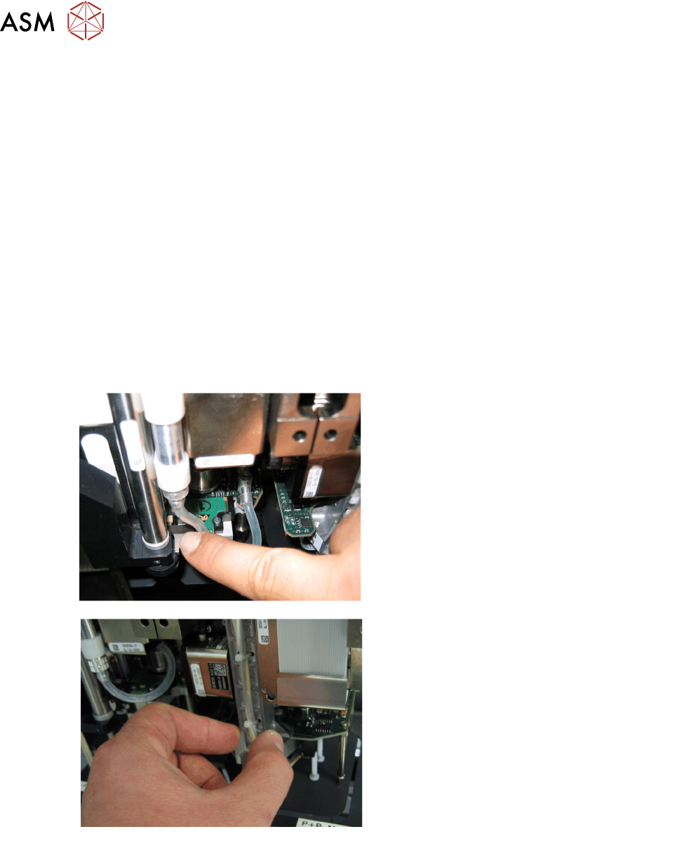
Lowering the Z Axis
Lowering the ZAxis at P&P Module1
To safely press the ZAxis downwards, apply
manual pressure to the marked part of the retract
unit driver.
Lowering the ZAxis at P&P Module2
The ZAxis can be moved downwards at segment
2 by taking hold of the carrier arm from both
sides and then pushing this down.
5 Placement Heads
5.3 Twin Head
Technical Training SIPLACE TX-Series 10/2016 141
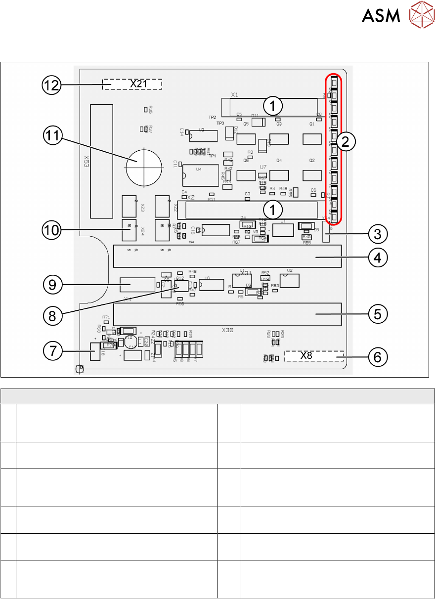
5.3.6 Board Description
Twin Head – Main Board Description Connectors
1 2 connectors for the 16 bit CAN Bus
processor (not used)
7 Power supply 15V for the Track signals
D- Axis (at the moment deactivated via the
jumper X54)
2 LEDs (see below) 8 EEPROM stores the head specific data
(head exchange, reference run)
3 X54 Jumper currently set to ON with the
new force measurement board set to OFF
(see LED V2/V_SP)
9 X4 Connector track signals Z Axis
4 Connector to the head adapter flat ribbon
cable
10 Connector pneumatic valve (retract unit)
5 Connector to the head adapter flat ribbon
cable
11 Hole for pneumatic pipe to the vacuum
generator
6 X8: Flex-Cable (Signals: Track signals
D Ax- is, Power supply Z Axis/D Axis, Z
Temperature and, SPI Bus)
12 X21 Connector for vacuum generator