00198168-02_Technical_Training_TX-Series_EN.pdf - 第143页
5 Placement Heads 5.3 Twin Head Technical Training SIPLACE TX-Series 10/2016 143 5.3.7 Calibration Twin Head – Calibration Overview Twin Head Calibration Tools & Nozzle Calibration tool 03010565 xx (1) - & Nozzle…
5 Placement Heads
5.3 Twin Head
142 Technical Training SIPLACE TX-Series 10/2016
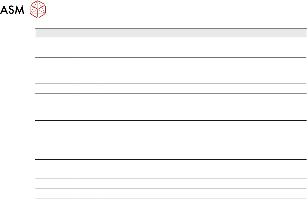
Twin Head – Main Board Description LEDs
LEDs (2) Description (Sequence Downwards)
LED Color Description
D8 Green Off – retract unit is moved out – LED shines briefly
D7 KLEMM Green On - display showing that the return cylinder has been projected
downwards.
D6 BERO Green Off - without function (previously: proximity switch Z Axis up)
D1 DRUCK Yellow Off - without function (Z pressure)
D2 KLEMM Yellow On – clamping Z Axis
Off – retract unit is at top position
V2/V_SP Green Shows the voltage supply 15 V for the D Axis track signals. Off – at jumper
setting ON and old force measurement board.
On – Twin Heads with new force measurement board have the 15V
regulated on the main board i.e. the jumper must be set to OFF and the
LED will be on.
V3 15V_ Green On – 15V for the D Axis track signals
V1 TEMP Green On - Z Axis motor temperature is OK
D14 ALARM Red Off – alarm output for vacuum generator On – vacuum generator defect
D9 DRUCK Green Off - without function (Z pressure)
D10 24V+ Green On – 24V for vacuum generator is OK
5 Placement Heads
5.3 Twin Head
Technical Training SIPLACE TX-Series 10/2016 143
5.3.7 Calibration
Twin Head – Calibration Overview
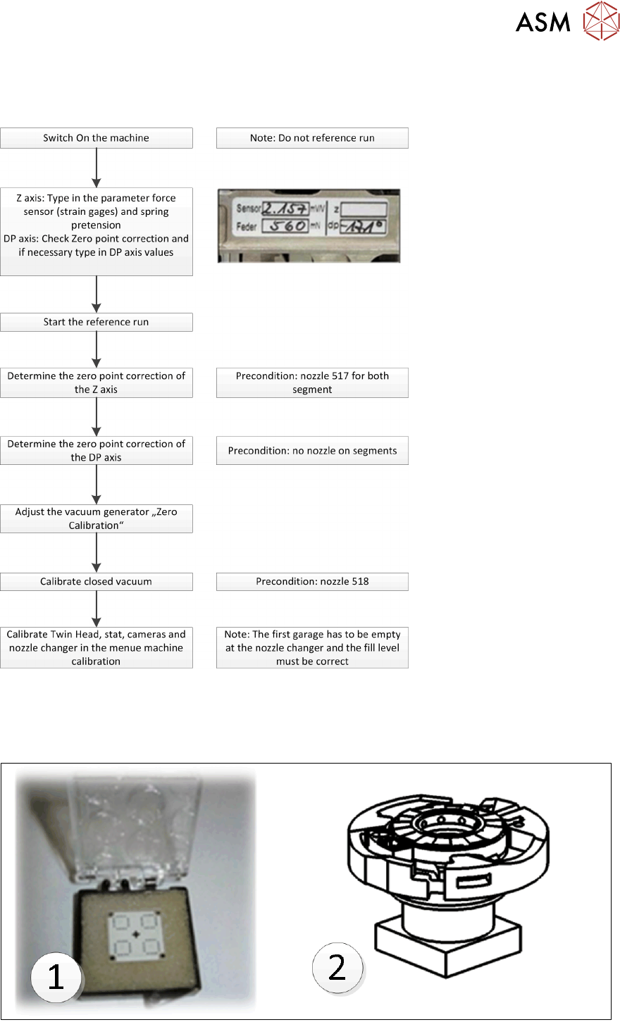
Twin Head Calibration Tools & Nozzle
Calibration tool 03010565 xx (1) - & Nozzle 517 / 518 for Head Calibration.
Calibration tool 03123022-xx (2) is required when calibrating the D-Axis zero point correction of
Twin Head using a Flip Chip Camera
5 Placement Heads
5.3 Twin Head
144 Technical Training SIPLACE TX-Series 10/2016
5.3.7.1 Pre Calibration Procedure
After performing a head exchange or service work on the Twin Head, the following settings are
required for successful calibration of the Twin Head.
1. Entering force Parameters
2. Calibrate Z zero point
3. Calibrate DP zero point
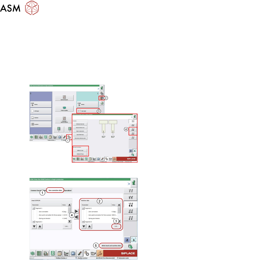
This can be done by selecting the Twin Head under the GUI menu “select sensors and functions of
specific components”.
1. Log on as "Service"
2. Click on Sensors and functions menu of
specific components.
3. Click Twin Head.
4. Icon for Z Axis and D Axis Selection
5. Icon for Z and DP Axes Zero point
corrections calibration.
Entering Force Parameters
1. Switch over to the Zero correction data tab.
Current values for both segments 1 and 2.
2. Mark the parameters at Machine data.
3. Click Edit... .
4. Apply the force parameters values from the
Head EEPROM with the arrow buttons (the
values can also be found on the label on the
Twin Head)
5. Click Write head and machine data to save
the values.