00198168-02_Technical_Training_TX-Series_EN.pdf - 第174页
7 Conveyor System 7.3 Conveyor Functionality 174 Technical Training SIPLACE TX-Series 10/2016 Shuttle functionality Single conveyor = > Dual conveyor Usually, the following right and then left conveyor lane are used i…
7 Conveyor System
7.3 Conveyor Functionality
Technical Training SIPLACE TX-Series 10/2016 173
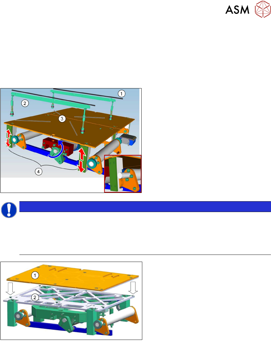
Board clamping unit
The distance between the top of the PCB board and the placement head is always the same for
each board, regardless of the board thickness. This has the following advantages.
●
The placement rate is not dependent on the PCB board thickness.
●
Fiducial recognition is optimized. The consistent space between the board upper edge and
the PCB camera means that the PCB camera is always focused on the upper side of the
board.
1. Conveyor rail
2. Clamping rail
3. Contact points
4. Lifting motor and mechanical device
NOTICE
TX micron 15 µm
In TX micron 15µm machines a lifting table stability reinforcer is installed to ensure a stable
position of the vacuum tooling.
Special feature:
Each vacuum tooling requires a lifting table limit that matches to the PCB thickness.
1.
2.
Lifting table plate
Lifting table stability reinforcer
7 Conveyor System
7.3 Conveyor Functionality
174 Technical Training SIPLACE TX-Series 10/2016
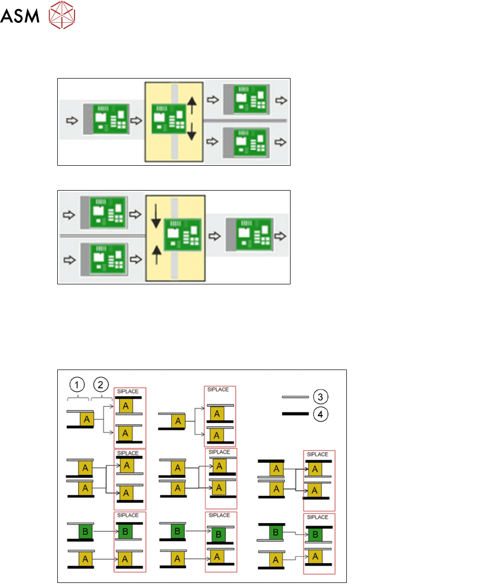
Shuttle functionality
Single conveyor = > Dual conveyor
Usually, the following right and then left
conveyor lane are used in alternation.
However, if a conveyor lane is blocked, the
other lane can also be used several times in
succession.
Dual conveyor = > Single conveyor
Usually, pickup is from the right and then the
left conveyor lane of the previous machine,
in alternation. However, if there is a problem
at one lane or if there is no board available,
pickup can also be from the other lane
several times in succession. Precondition:
the same product must be produced on both
lanes.
Shuttle modes
●
Same PCB “A” in both lanes 1 and 2 machine runs in i=placement mode or asynchronous
mode.
●
Two different PCBs “A” and “B” in lane 1 “A” and lane 2 “B” machine runs in i-placement mode
or asynchronous mode.
1. Predecessor
2. Shuttle
3. Moveable rail
4. Fixed rail
For detailed information refer to the shuttle user manual.
7 Conveyor System
7.3 Conveyor Functionality
Technical Training SIPLACE TX-Series 10/2016 175
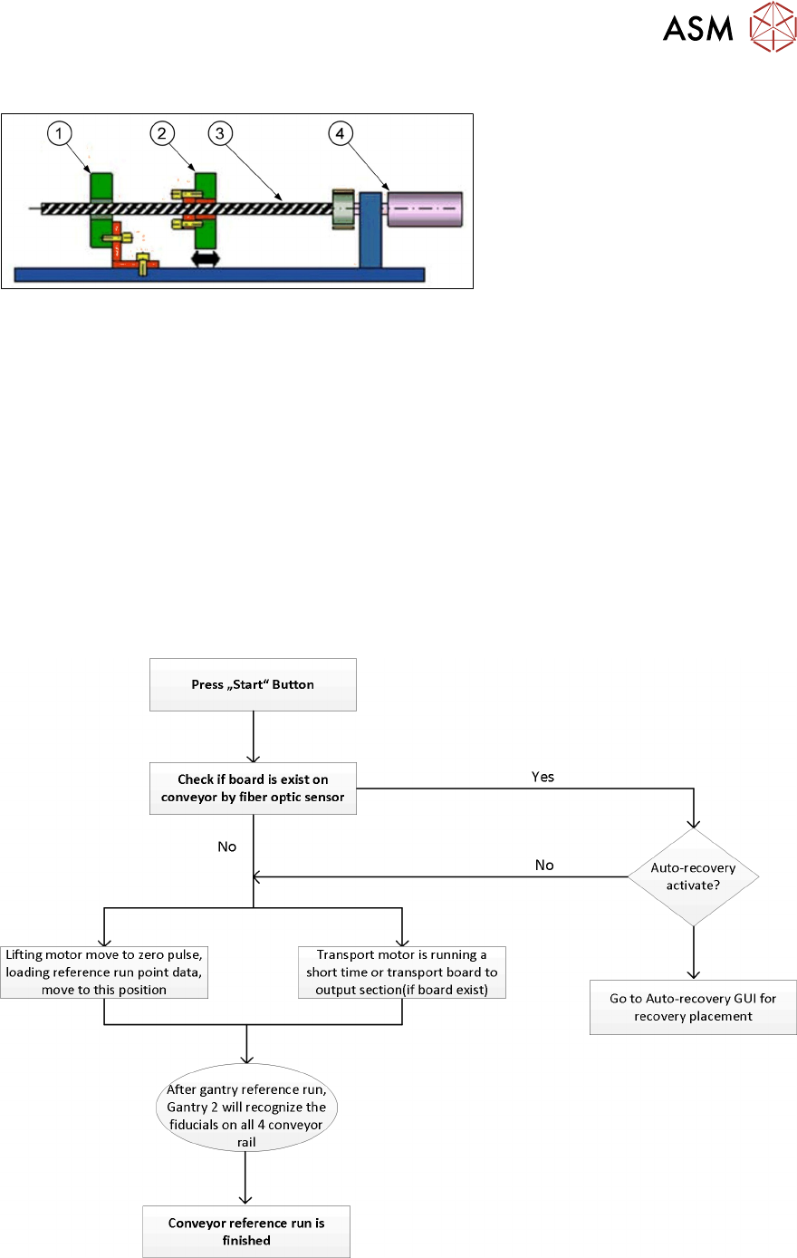
7.3.2 Width adjustment
1. Fixed conveyor side
2. Flexible conveyor side
3. Ball screw
4. Motor with belt system
During normal production the width adjustment is set automatically upon product change by
SIPLACE Pro. Manual width adjustment is possible by means of the station software.
The width adjustment is performed with a stepping motor and two ball screws. In a dual conveyor,
different widths are possible for the two conveyor lanes.
During reference run, the conveyor rails edges will be recognized by PCB camera.
Conveyor width is measured by counting system of the motor, if the conveyor width is adjusted
manually with the machine turned off, it may happen that the actual width and the width set in the
station software no longer match and the conveyor width will have to be set.
This can be done using the "find fiducial position" in the station software.
7.3.3 Reference run
During the machine reference run the conveyor system is initialized. This is done after the gantry
reference run is completed. The light barrier and laser light sensitivity is measured and recorded for
use during PCB recognition.
During the reference run the software checks if the rail positions have been changed and issues an
estimated position for each rail. After that the board camera drives to each of the 4 fiducials on the
conveyor rails to determine the exact position and the exact conveyor width.