00198168-02_Technical_Training_TX-Series_EN.pdf - 第213页
8 Power Supply 8.9 US option Technical Training SIPLACE TX-Series 10/2016 213 8.9 US option All the power packs used in the SMPS of series QT40 have a permissible input voltage of 380V – 480V. In case of mains voltages b…

8 Power Supply
8.8 Analysis - Common Error List
212 Technical Training SIPLACE TX-Series 10/2016
Error Possible Cause Action
DC24-S is missing Fuse does not work?
Connector X24A (both PCB’s!)
properly connected?
●
Check supply voltage at
FD.A1, F11
Fuse blown or broken?
●
Replace fuse
●
Place connector firm into
place
If error still occurs
→ internal defect of CSB:
●
Replace unit
POWER-Enabled sig-
nal is missing
Fuse does not work?
Connector X24A (both PCB’s!)
properly connected?
Precharge sequence finished?
DC link voltages are ON)?
●
Check supply voltage at
FD.A1, F11
Fuse blown or broken?
●
Replace fuse
●
Place connector firm into
place
If error still occurs
→ internal defect of CSB:
●
Replace unit
Errors at diagnostic interface:
Error Possible Cause Action
No diagnostic display
(Icon is missing)
Wiring of diagnostic master:
●
Connection between PS1 and
CAP established?
●
Connection between CAP and
IOCU2 established (use
crossover cable!)?
●
Replace wiring.
If there is still no Diagnostic display
available → Diagnostic master at
CAP unit failure:
●
Replace CAP unit
●
QT40 diagnostic supply
voltage available?
●
Internal fuse at CAP unit
blown?
Voltage reading between Pin 1 and
4 of diagnostic connector should be
DC 5V
●
Check QT40 diagnostic supply
voltage.
●
Check internal fuse at CAP
unit.
●
Check voltage reading
between Pins 1 and 4 of
diagnostic connector.
If there is no voltage reading →
CAP unit failure:
●
Replace CAP unit
No fuse diagnostic dis-
play
Wiring to FD.A1:
Connection between FD.A1 and
IOCU2 establisched?
●
Check if FD.A1-X3 is located
firm in its place.
If not:
●
Replace wiring
If there is still no Fuse diagnostics
available:
→ FD.A1 internal error.
●
Replace FD.A1
8 Power Supply
8.9 US option
Technical Training SIPLACE TX-Series 10/2016 213
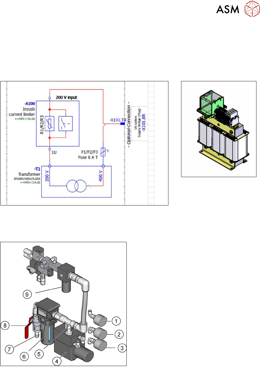
8.9 US option
All the power packs used in the SMPS of series QT40 have a permissible input voltage of 380V –
480V.
In case of mains voltages below 360 VAC (3*200 - 230 V AC) voltage adaption to input voltages
380 - 480 VAC has to be provided. This is done by an US voltage adaption kit.
The transformer is found in the machine base close to the Box PC.
8.10 Pneumatic System Overview
Pneumatic System – Parts Overview
1. Pressure gauge for supply pressure of the
machine components (5 ± 0,25 bar)
2. Pressure gauge for supply pressure of the
Gantry 1/2 (4,85 ± 0,1 bar)
3. Pressure gauge for input air (5.0 – 10.0
bar)
4. Proportional valve
5. Compressed air supply for gantries
6. Compressed air filter
7. Compressed air input
8. Stop Valve
9. Pressure regulator
8 Power Supply
8.10 Pneumatic System Overview
214 Technical Training SIPLACE TX-Series 10/2016
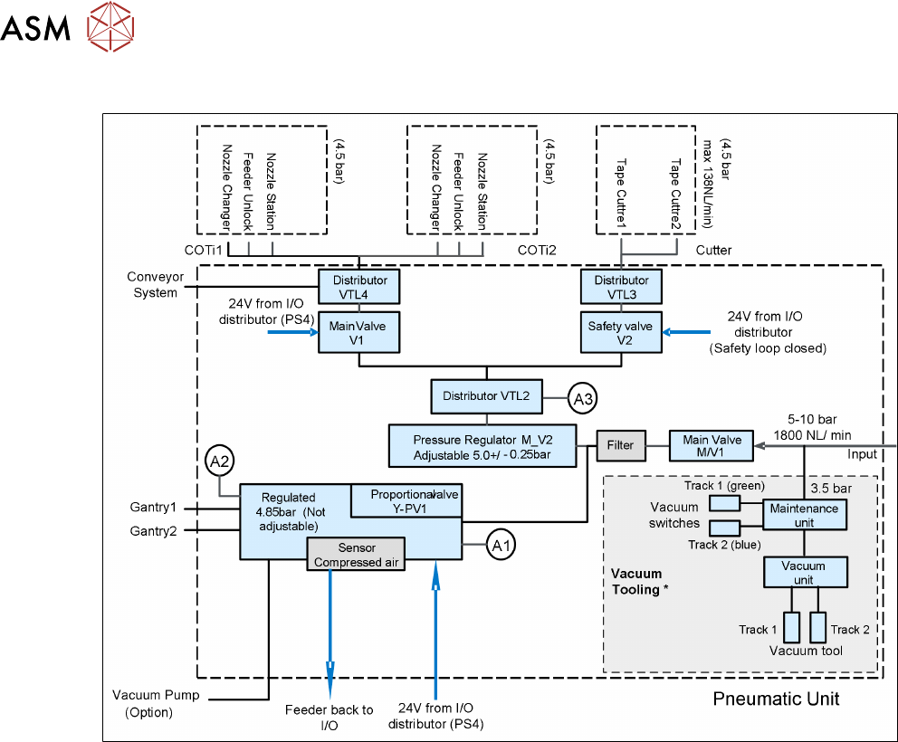
Overview Pneumatic Diagram
* Only for TX machines with installed vacuum tooling.
For detailed information about setting up the vacuum tooling refer to the installation manual
"Basic-Pack Vacuumtooling", order number 03149358-01.