00198168-02_Technical_Training_TX-Series_EN.pdf - 第221页
9 Control and Communication 9.2 Machine Communication bus Overview Technical Training SIPLACE TX-Series 10/2016 221 Overview CAN bus Overview of machine CAN bus participants CAN bus loop 1 CAN bus loop 2 CAN bus loop 3 M…
9 Control and Communication
9.2 Machine Communication bus Overview
220 Technical Training SIPLACE TX-Series 10/2016
9.2 Machine Communication bus Overview
The TX machine is using three different bus systems:
MCAN (Machine CAN bus)
The MCAN-bus is responsible for the communication between the Box PC and the different
subsystems within the machine.
GCAN (Gantry CAN bus)
The GCAN-bus is responsible for the communication between the gantry control unit´s (MGCU´s)
and the head control unit´s (MHCU´s) (e.g. Head-CAN-Diagnostics or SIRIO-Communication).
FDB GCU (Fast Drive bus GCU)
The Fast Drive bus GCU is a straight connection between the two GCU´s which are responsible for
the gantry synchronization (anti crash).
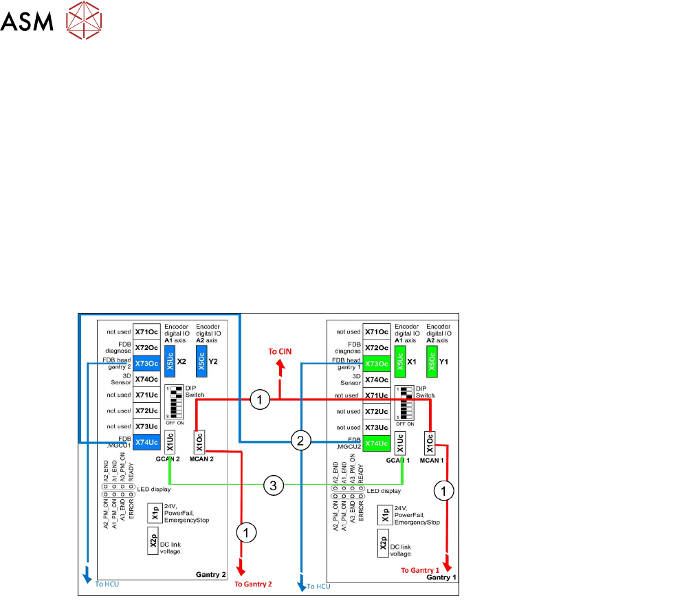
1. MCAN (Machine CAN bus)
2. Fast Drive bus (FDB)
3. GCAN (Gantry CAN bus)
and also to training –
interface 1/2
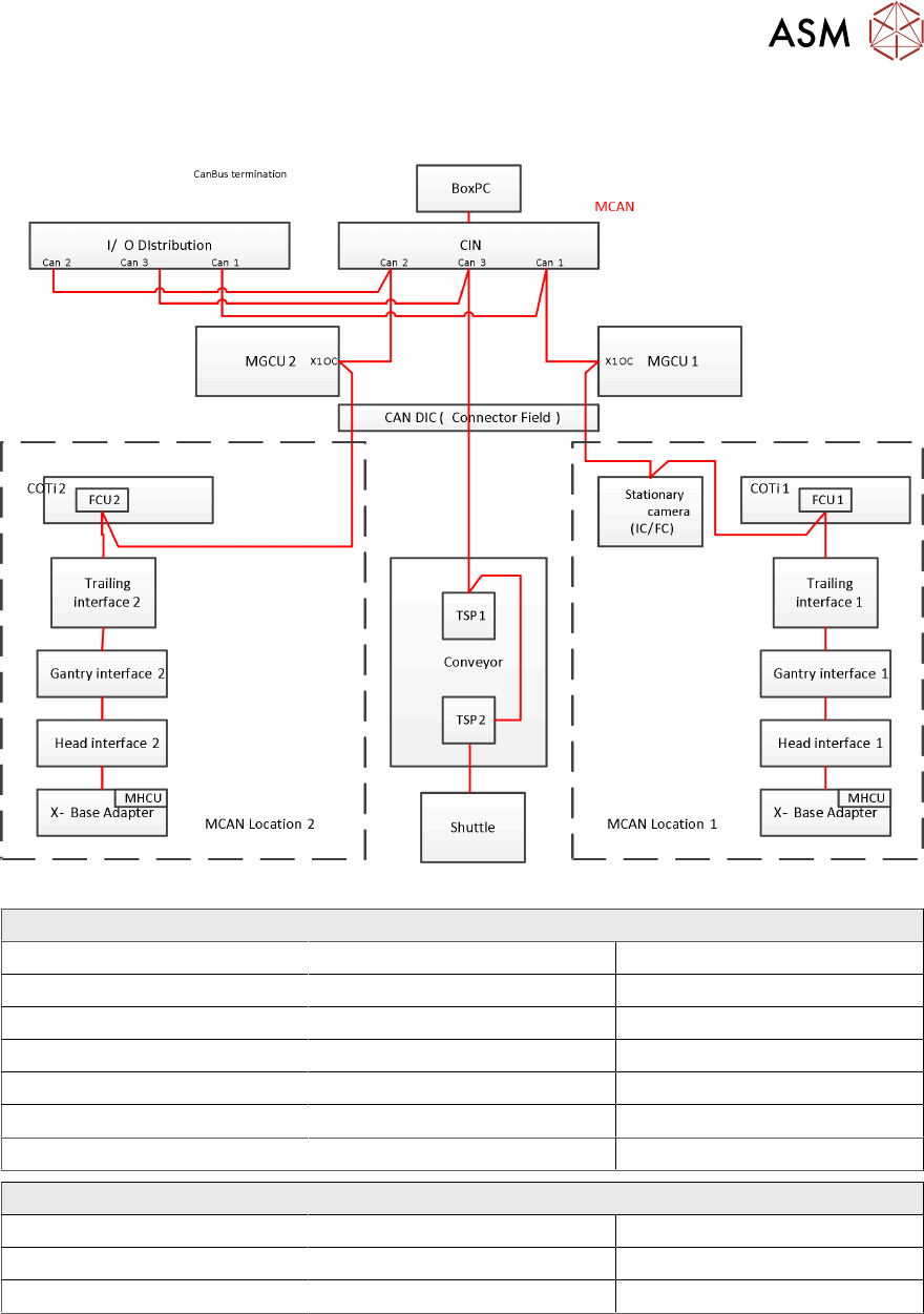
MCAN (Machine CAN bus)
TX machines run with three separate CAN bus loops (CAN1 / CAN2 /CAN3).
The CAN bus runs with a speed of 1 MBit/s.
The CAN Interface (CIN) (instead of CAN card of the Box-PC) serves as a interface to BoxPC /
SIRIO.
9 Control and Communication
9.2 Machine Communication bus Overview
Technical Training SIPLACE TX-Series 10/2016 221
Overview CAN bus
Overview of machine CAN bus participants
CAN bus loop 1 CAN bus loop 2 CAN bus loop 3
MGCU 1 (primary axis) MGCU 2 (primary axis) I/O unit (input-/ output module)
MHCU1 (head axis) MHCU1 (head axis) Conveyor controller (TSP)
I/O unit (input-/ output module) I/O unit (input-/ output module) Shuttle extension
Stationary camera COTi2 / FCU2
COTi1 / FCU1
CIN Box CIN Box CIN Box
Head CAN bus 500KBit/s
Pressure control valve (C&P20) Holding circuit sensor Bottom light sensor
DP station (CPP/C&P20) SCS
Valve block (CPP) EEPROM Z/Star Axis
9 Control and Communication
9.3 MGCU and MHCU
222 Technical Training SIPLACE TX-Series 10/2016
GCAN (Gantry CAN bus)
The TX machines run with machine CAN bus also second additional gantry CAN bus.
The gantry CAN bus provides the communication for synchronization between the Gantry Control
Units (MGCUs) and the Head Control Units (MHCUs).
GCAN bus participants
MGCU 1/2 (main axis) and MHCUs (head axis).
Fast Drive bus (FDB)
Additionally to the machine and gantry CAN bus system, TX machines use a Fast Drive bus (FDB).
Due to the decentralised drive concept, this CAN system is used for the faster data exchange
between MHCUs and MGCUs, providing extremely fast communication to control the axis, using
transfer rates of 20 Mbit/s (in contrast to the MCAN & GCAN bus with 1 Mbit/s).
The FDB enables you to adapt the data for the drives very flexibly or rather to implement new
functions.
The FDB is completely independent of the machine CAN bus.
9.3 MGCU and MHCU
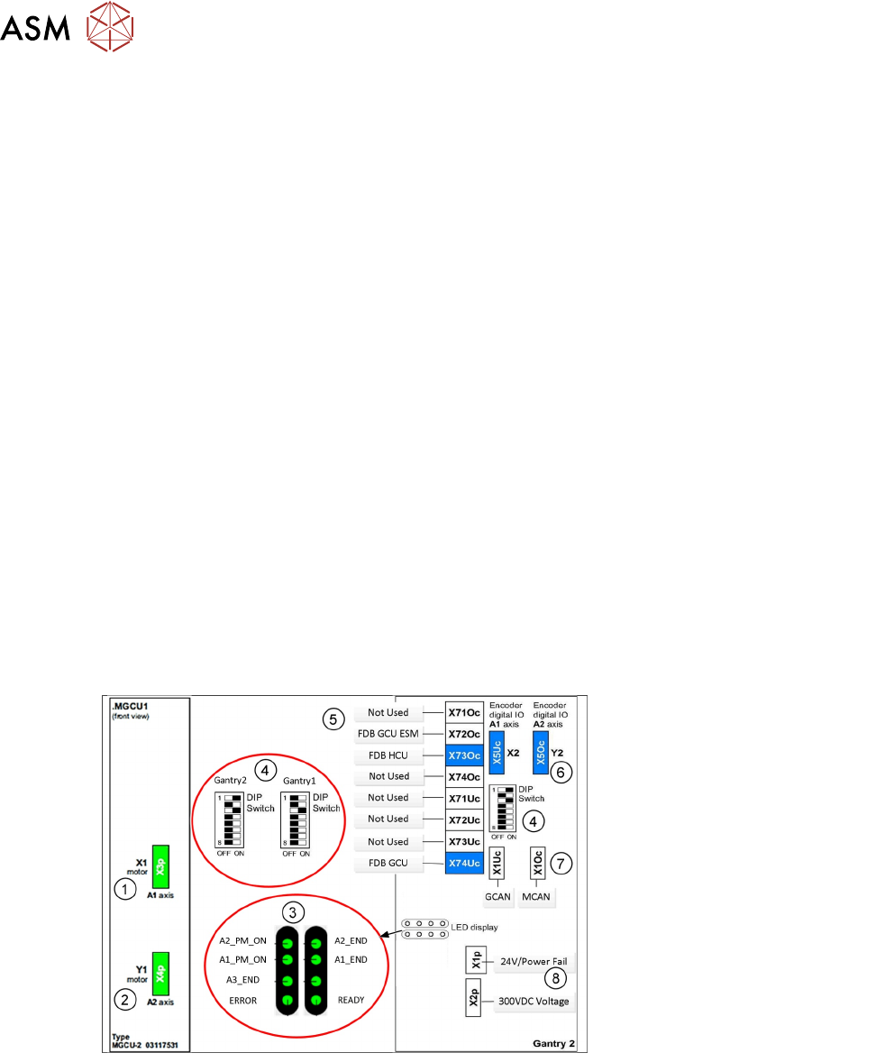
MGCU (Modular Gantry Control Unit):
MGCU is used for controlling of the gantry main axes X & Y; it consists of a control module (CM)
and a power module (PM), comparable to the axis card as control module and the servo card as
power module.
Depending on the MGCU type it can control 2 gantry axis (MGCU2) or 3 gantry axis (MGCU3),
MGCU2 is used on TX machine as controller of the main axes (X/Y axis) of gantry (one MGCU2 for
one gantry).
1. X Motor connection
2. Y Motor Connection
3. LEDs
4. DIP Switches
5. BUS connections
6. X/Y Track Signal connector
7. MCAN and GCAN
8. 24V power fail and 300VDC
link
MHCU (Modular Head Control Unit)
MHCU is used for controlling of the head axes (Star/Z) it also consists of a control module (CM)
and a power module (PM).