00198168-02_Technical_Training_TX-Series_EN.pdf - 第224页
9 Control and Communication 9.5 CIN Box 224 Technical Training SIPLACE TX-Series 10/2016 9.5 CIN Box ● In TX-Series machines the, "CAN Interface" CIN [03108598-xx] is used to take over the function of CAN Card …
9 Control and Communication
9.4 Box PC (Control Computer)
Technical Training SIPLACE TX-Series 10/2016 223
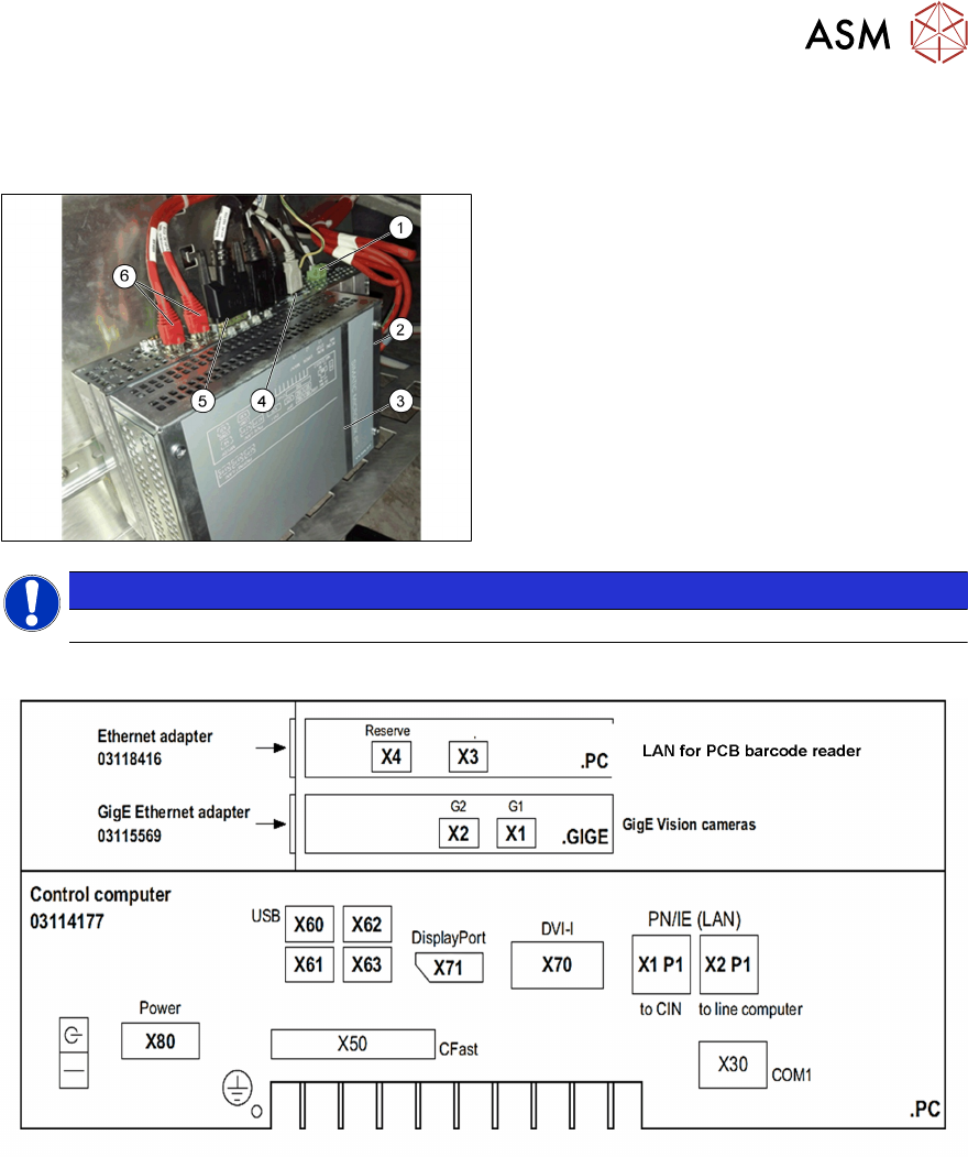
9.4 Box PC (Control Computer)
Box PC 427D
1. Power 24VDC
2. GigE connection
3. Box PC 427D (03114177-xx)
4. USB connectors
5. Display Port for monitor 1
DVI for monitor 2
6. LAN1 CIN‐Box (CAN‐Bus)
LAN2 line computer
NOTICE
After replacing the BoxPc with new one, the station SW needs to be installed.
Control computer SIPLACE TX
Different ports for different monitors, “DisplayPort” (X71) for monitor1 (Power supply side) and
“DVI-I” (X70) for monitor 2.
Before the successful installation of the SW, different displays are shown on each monitor.
9 Control and Communication
9.5 CIN Box
224 Technical Training SIPLACE TX-Series 10/2016
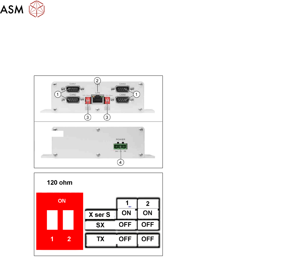
9.5 CIN Box
●
In TX-Series machines the, "CAN Interface" CIN [03108598-xx] is used to take over the
function of CAN Card in the previous machines.
●
CIN located in the SMPS and connected to the BoxPC-427D via a LAN cable.
●
For TX machine, the CAN termination on CIN always setting as "OFF".
1. CAN connections 1-4
2. LAN connection
3. DIP switches - setting the terminator of
120 Ohm for CANx-
Note:
The DIP switch settings (see below) are
valid for both DIP switches.
4. Power Input
DIP switch settings
9 Control and Communication
9.6 Network Construction
Technical Training SIPLACE TX-Series 10/2016 225
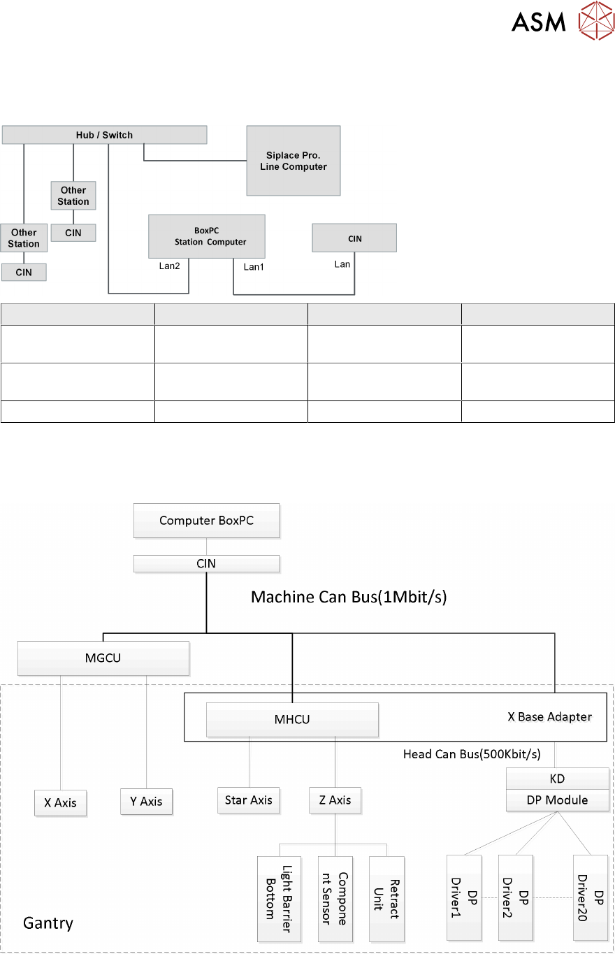
9.6 Network Construction
Network Construction
IP address Subnet mask Comment
SIPLACE Lan 172.22.xxx.xxx 255.255.0.0 LAN connection on the
computer
CIN 192.168.255.239 255.255.255.224 LAN connection on the
computer
Station computer 192.168.255.249 255.255.255.224
9.7 Axis Control
Axis Control