00198168-02_Technical_Training_TX-Series_EN.pdf - 第227页
9 Control and Communication 9.9 Feeder Communication Technical Training SIPLACE TX-Series 10/2016 227 Control and Communication – FCU Overview 9.9 Feeder Communication The communication between the Feeder Control Unit (F…
9 Control and Communication
9.8 FCU
226 Technical Training SIPLACE TX-Series 10/2016
9.8 FCU
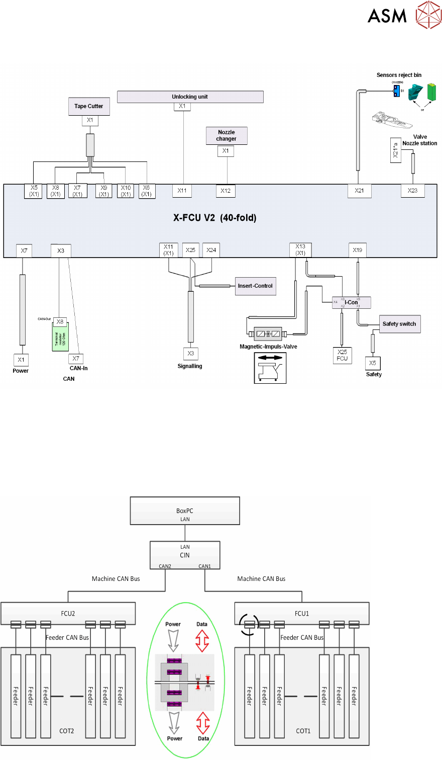
The FCUs (Feeder Control Unit) on TX machines has the basically functionality:
●
Communication with the feeders and docking of the COT.
●
Control of the tape cutter (moving the pneumatic cylinders in and out, status query of the
sensors).
●
Nozzle changers detection and the nozzle station (forced air valve for the C&P20 and CPP)
control.
●
Query of the sensors for the component/nozzle reject boxes.
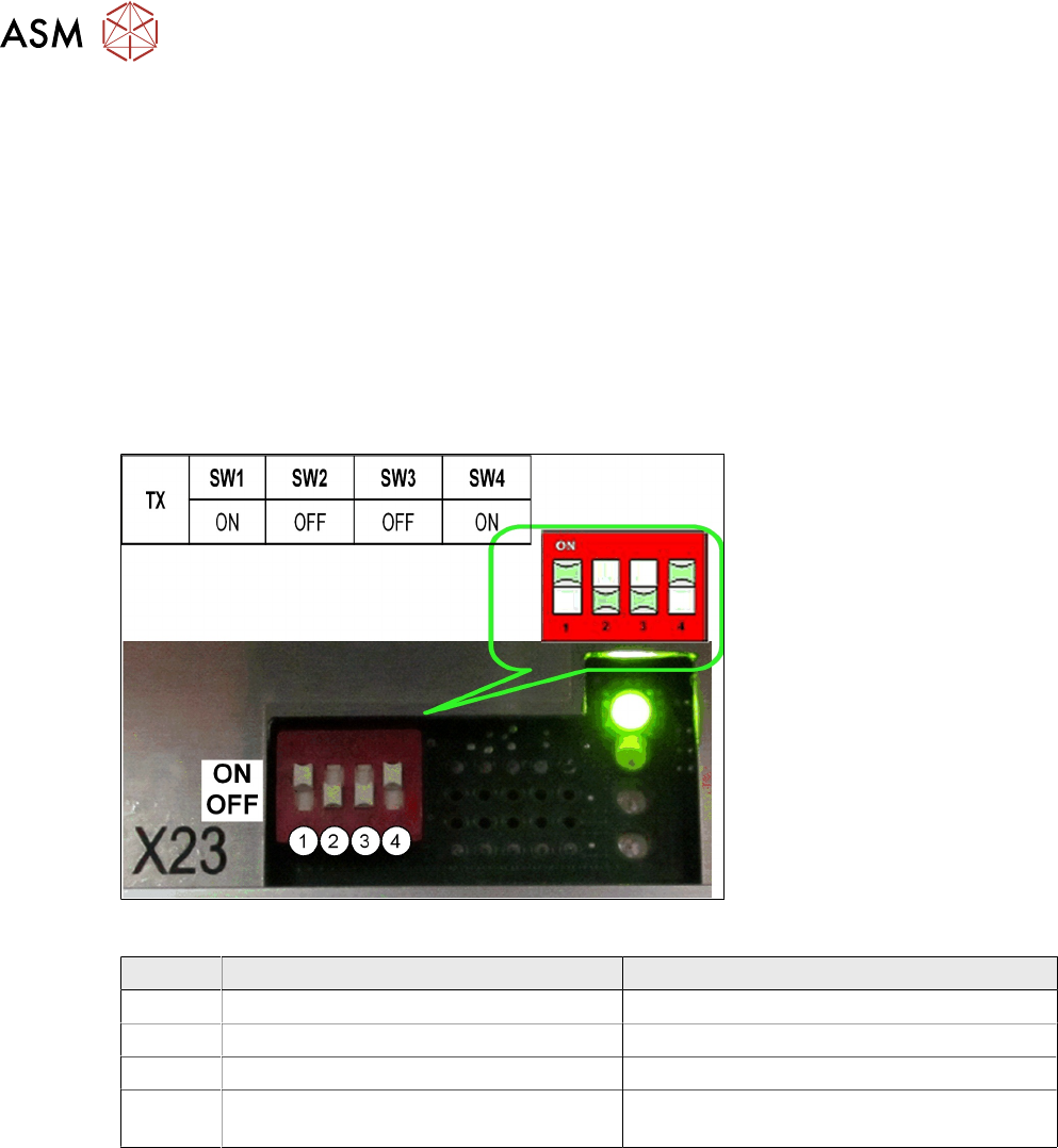
During production with (SW1= OFF) the reject bin is recognized by the sensor and signalized by
the LED.
The FCU need to be addressed for the TX see diagram below:
Switch settings
ON OFF
SW1 Test mode for reject bins deactivated Test mode for reject bins activated
SW2 60 Fold FCU 40 Fold FCU
SW3 Without insert control with virtual button With insert control without virtual button
SW4 HW version 8 with tape cutter and nozzle
changer functions
HW version without tape cutter and nozzle
changer functions
9 Control and Communication
9.9 Feeder Communication
Technical Training SIPLACE TX-Series 10/2016 227
Control and Communication – FCU Overview
9.9 Feeder Communication
The communication between the Feeder Control Unit (FCU) and the X-feeders is carried out via an
internal CAN bus.
This CAN bus is only responsible for the communication between the FCU and the feeders and is
controlled by the machine CAN bus.
The data and power supply from the FCU to each feeder is contactless.
9 Control and Communication
9.10 VISION GigE
228 Technical Training SIPLACE TX-Series 10/2016
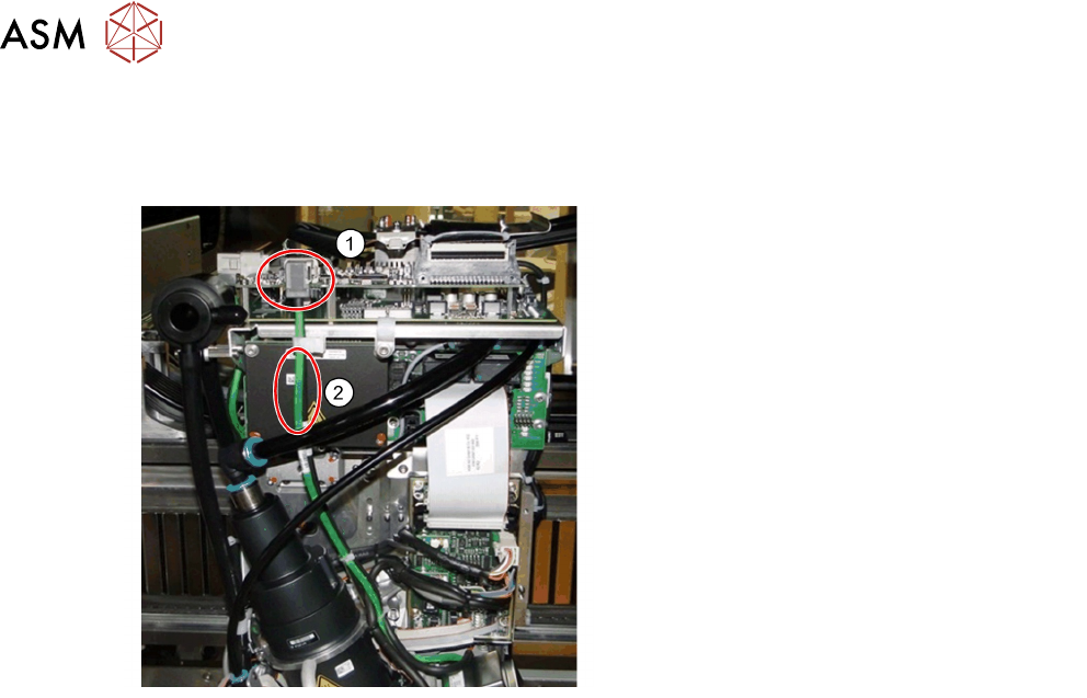
9.10 VISION GigE
GigE is the term used for the vision system hardware including camera types and a bus structure
on TX machine.
1. Ethernet connectors
2. Communication via Ethernet cable
(may be black or green)
●
GigE is an interface standard for high-performance industrial cameras. It provides a
framework for transmitting high-speed video and related control data over Ethernet networks.
●
It’s incompatible to the existing SIPLACE Vision System Hardware.
●
A GigE-network interface card (Ethernet Adapter) is inside the BoxPC.
●
All GigE cameras use the same sensor type number as for SIPLACE Vision with an additional
G at the end, e.g. SST23G.
The Vision communication on TX over GigE and CAN bus
●
The images from the Component and PCB cameras are sent digitally to the Vision Base
Interface (VBI).
●
The transfer takes place via the trailing cable “Spread Spectrum“ (without coax cable).
●
The images from the IC and FC cameras are sent directly to the GigE adapter in PC via the
Vision base Interface (VBI).
●
The machine CAN bus provides the illumination control.
●
The individual illumination values stored in the component shape are transferred to the
camera via CAN bus.