00198168-02_Technical_Training_TX-Series_EN.pdf - 第42页
4 Gantry System 4.3 Calibration after Repair and Adjustment 42 Technical Training SIPLACE TX-Series 10/2016 4.3.2 Conducting Calibrations 1. Log on as Machine service (1-3). 2. Click Calibration (1). Click Automatic cali…

4 Gantry System
4.3 Calibration after Repair and Adjustment
Technical Training SIPLACE TX-Series 10/2016 41
4.3 Calibration after Repair and Adjustment
4.3.1 Explanation of main Gantry Calibrations
Zero point offset (machine Zero Point Correction)
The machine ZPC (station point for each gantry) is used as point of reference for the X/Y Axis to
the machine coordinate system. Thus the axes know their current positions in the machine. The
PCB camera moves towards this machine zero point (fiducial). Then the X/Y directions are
measured. The resulting offset is taken into account in the fixed zero point correction of the X/Y
Axis.
Travel range
The axis concerned moves as far as possible towards the minimum or maximum position and the
limit is set.
System identification
Checks the controls parameters of the X/Y Axis to ensure reliable control of the axis movement.
The procedure should be repeated if the machine has been moved or if gantry conversion has
been done.
X Axis parametrization
Optimizes the X Axis control parameters.
Board camera (PCB camera)
Determines the calibration factors, the relation of the camera pixel size to the resolution of the
machine measurement system (X, Y) and the mounting angle of the CCD sensor in the PCB
camera.
4 Gantry System
4.3 Calibration after Repair and Adjustment
42 Technical Training SIPLACE TX-Series 10/2016
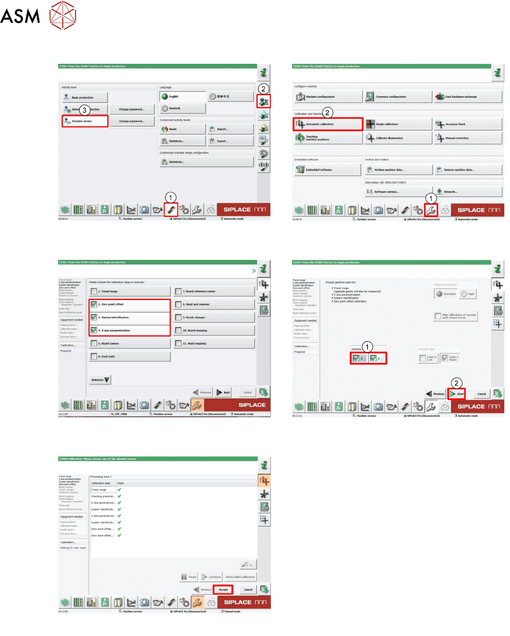
4.3.2 Conducting Calibrations
1. Log on as Machine service (1-3). 2. Click Calibration (1).
Click Automatic calibration (2).
3. Select required calibration item. 4. Select required Gantry (1).
Click Start (2).
5. Click Accept to save data.
4 Gantry System
4.4 PCBs
Technical Training SIPLACE TX-Series 10/2016 43
4.4 PCBs
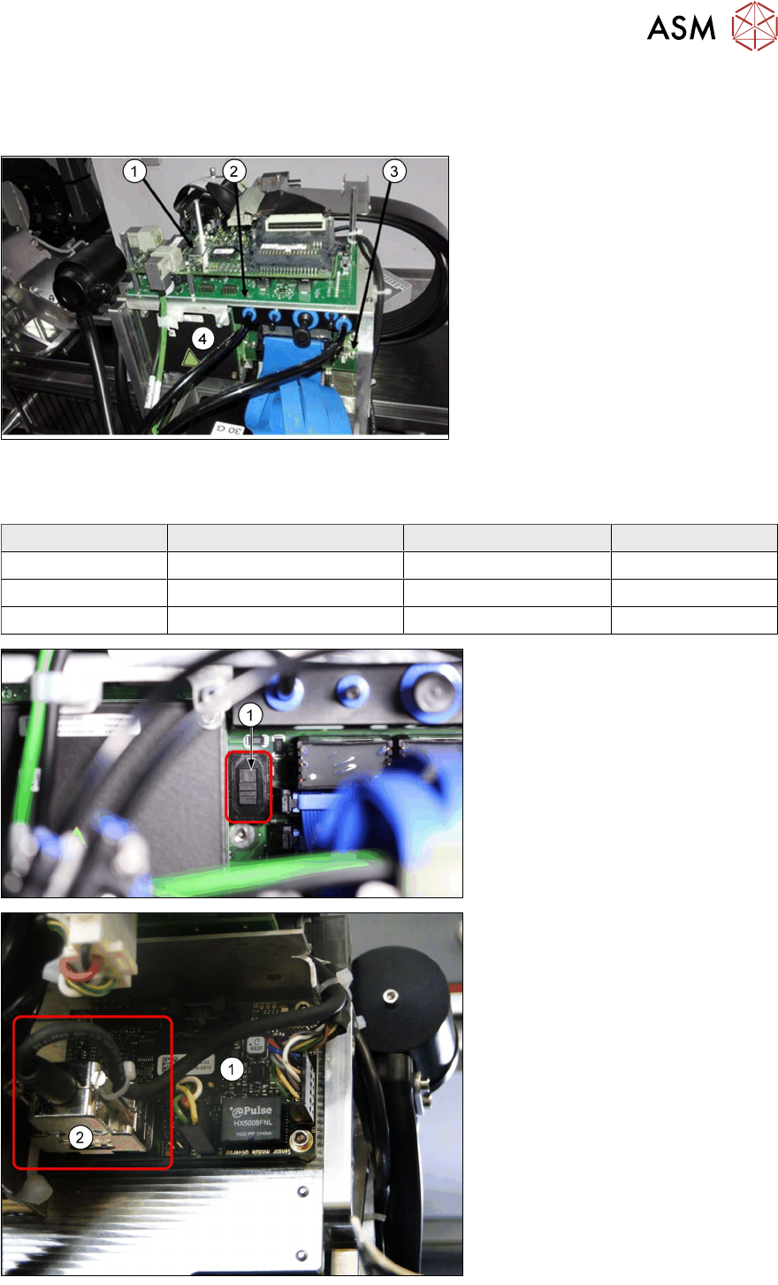
Head Board Complete (with MHCU)
1. Vision Head Interface (VHI)
2. Head interface
3. Base adapter with MHCU (4)
4. MHCU
Base adapter boards
Two kinds of base adapter boards depending on head type.
Head Type Head Interface Base Adapter MHCU
CP20x Head Interface TX (R/L) Base Adapter C&P 1x
CPP Head Interface TX (R/L) Base Adapter C&P 1x
Twin Head Head Interface TX (R/L) Base Adapter TH 2x
Base adapter C&P board
1. "Switch to set the voltage for
ZAxis of CP20x (40V) or CPP
(150V).
1. Sensor module board
2. Plug for reading unit XAxis.
(Micron machines only)