00198168-02_Technical_Training_TX-Series_EN.pdf - 第54页
5 Placement Heads 5.1 CPP Head 54 Technical Training SIPLACE TX-Series 10/2016 5.1.2.2 DP Drive 1. Vacuum / Air kiss connection 2. Motor 3. The connector screwed to the SCS control unit 4. Nozzle interface 5. Camera back…
5 Placement Heads
5.1 CPP Head
Technical Training SIPLACE TX-Series 10/2016 53
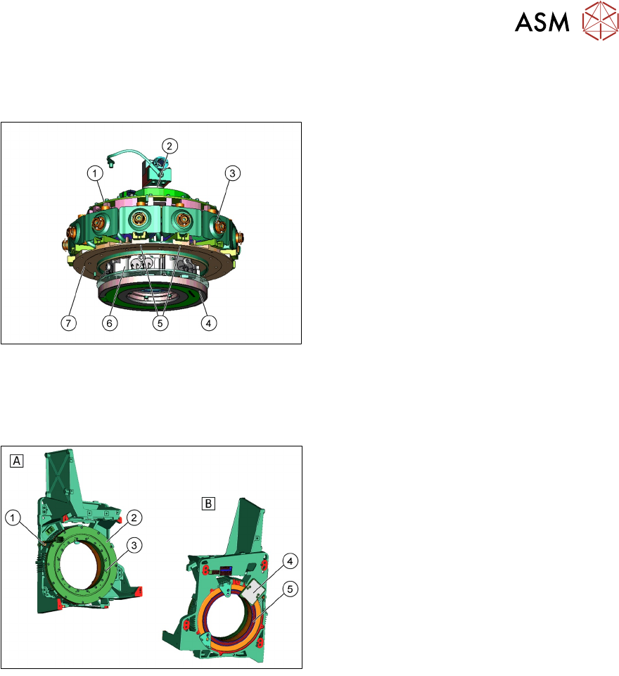
5.1.2 Main Parts/Unit Overview
5.1.2.1 Star
1. Single Core Solution (SCS)
2. Holding circuit in center of star
3. DP drives
4. ED transmitter 24V (contactless energy
transfer)
5. Fixture on rotor of star motor
6. Valve terminal/board
7. Star frame
●
The star consists of the star frame, on which the 12 DP drives are located, the control board
(Single Core Solution), the valve terminal and the E/D transmitter.
●
The holding circuit is in the center of the star.
Star Motor
A Exterior View
1. Lubricate position Star bearing
2. Stator Star Motor
3. Rotor Star Motor / Interface for fixing the
star frame
B Interior View
4. Reader head measuring system
5. Incremental measuring system
●
The motor functions contact free i.e. there is no wear and tear.
●
The head casing also serves as the motor casing.
●
The star motor is not a spare part and can not be replaced.
5 Placement Heads
5.1 CPP Head
54 Technical Training SIPLACE TX-Series 10/2016
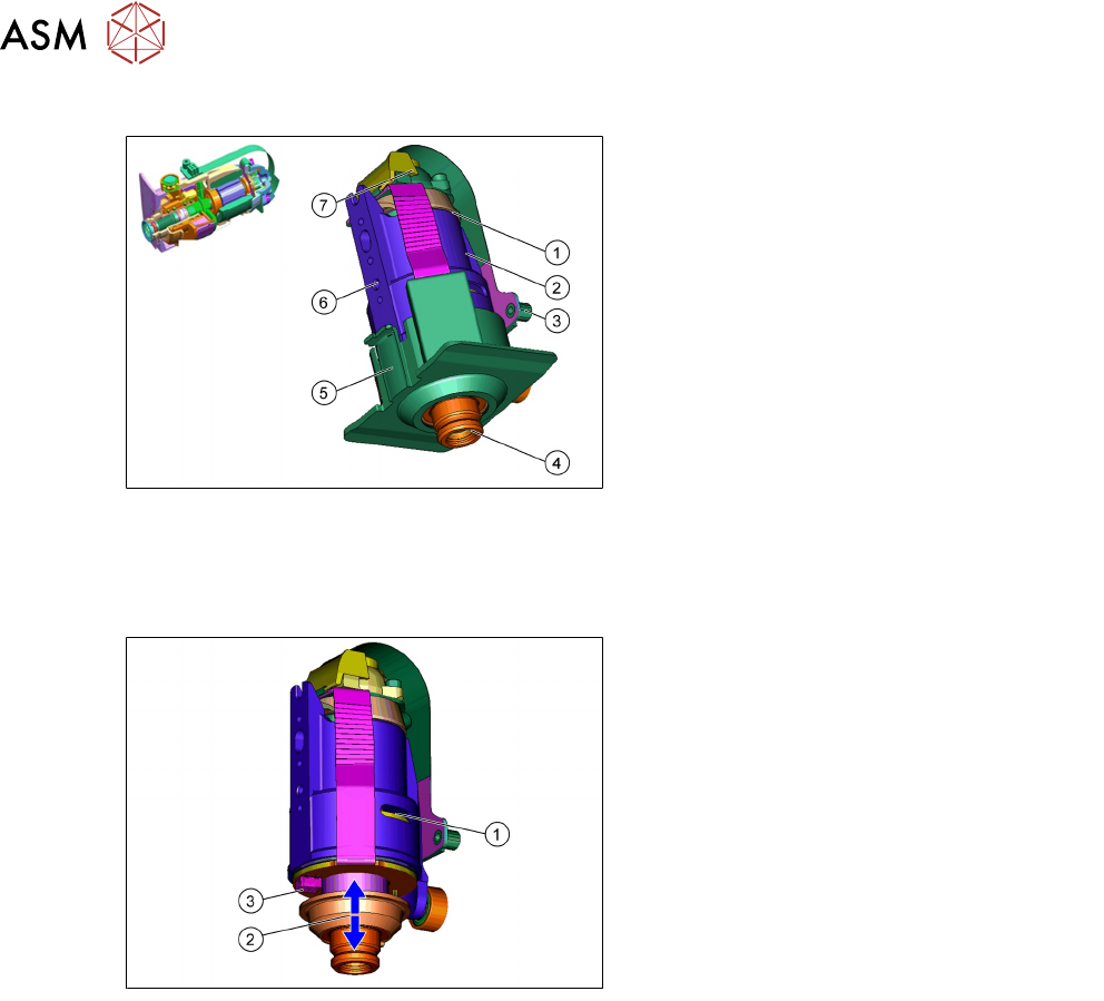
5.1.2.2 DP Drive
1. Vacuum / Air kiss connection
2. Motor
3. The connector screwed to the SCS control
unit
4. Nozzle interface
5. Camera background (black) for DP drive
6. Mounting surface for screwing the linear
guide
7. Measuring system
●
The DP drive is responsible for turning the nozzles into the correct pickup position and the
component into the correct placement angle.
●
Vacuum and air blast to the nozzle are provided via the motor shaft of the DP Axis.
●
The complete DP drive can be replaced during service work.
1. Measuring system
2. Cushioning path for operating the light
barrier down
3. Light barrier down
DP Drive function
●
The DP drives are controlled by the SCS board, in accordance with the counter pulse and
nominal value (pickup angle, placement angle and correction angle after Vision).
●
The feedback about the position of the DC motor is monitored by an incremental measuring
system.
Light barrier bottom
●
Each DP drive has its own light barrier down sensor. When the Z Axis springs into place, the
sensor sends a signal to the axis controller board (MHCU).
●
The "light barrier down" signal is directly linked to the measurement signal of the Z Axis
incremental encoder.
5 Placement Heads
5.1 CPP Head
Technical Training SIPLACE TX-Series 10/2016 55
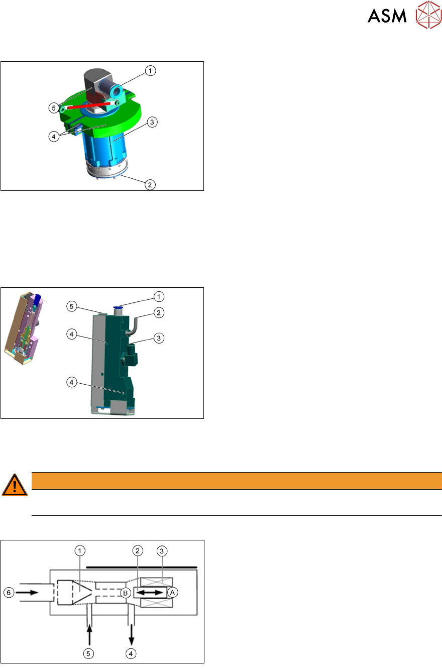
5.1.2.3 Vacuum CPP Holding Circuit
1. Input compressed air 4.5 bar
2. Frame with venturi nozzles
3. Screws to fix on the star frame
4. Two part silencer and mounting parts
5. Swivel joint with contact ring
●
The holding circuit consists of 12 small venturi nozzles.
●
Compressed air with a min pressure of 4.5 bar, each venturi nozzle supplies one segment
with vacuum.
●
If a segment is in the pickup/placement circuit, the hold circuit vacuum is increased (for
pickup) or eliminated via air kiss (for placement).
5.1.2.4 Pressure Regulator Valve (PRV)
1. Compressed air connection
2. Vacuum/air kiss for pickup/placement circuit
3. Discharged air, for cooling the X-linear motor
4. Mounting the vacuum generator on the front
plate
5. Energy and data supply
●
The pressure control valve supplies the pickup/placement circuit with vacuum/air kiss during
the pickup/placement process.
●
The PRV can be replaced during service work.
WARNING
Two screws M4x30 and M4x35 for fixing the pressure control valve. Interchange the screws
will destroy the SCS board.
Pressure Regulator Valve Functionality
1. Venturi nozzle
2. Plunger (iron core)/ piston
3. Plunger drive (inductor)/ driver circuit
4. Discharged air to silencer
5. Vacuum or air kiss output
6. Compressed air input
A - Piston in "open" position
B - Piston in "closed" position
●
During pickup, the piston is always in the "open" position; vacuum is produced and applied to
nozzle for pickup.
●
During placement, the piston is in the "close" position, air kiss is produced and applied to
nozzle for placement.
●
In the placement cycle the time to switch between maximum vacuum (-850 mbar) to maximum
air kiss (+400 mbar) is < 12ms.