00198168-02_Technical_Training_TX-Series_EN.pdf - 第56页
5 Placement Heads 5.1 CPP Head 56 Technical Training SIPLACE TX-Series 10/2016 5.1.2.5 Intermediate Distributor The intermediate distributor consists of two boards: 1. Intermediate distributor 1 is fitted to the front of…
5 Placement Heads
5.1 CPP Head
Technical Training SIPLACE TX-Series 10/2016 55
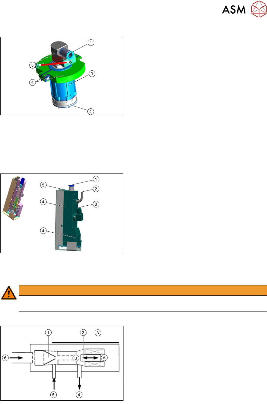
5.1.2.3 Vacuum CPP Holding Circuit
1. Input compressed air 4.5 bar
2. Frame with venturi nozzles
3. Screws to fix on the star frame
4. Two part silencer and mounting parts
5. Swivel joint with contact ring
●
The holding circuit consists of 12 small venturi nozzles.
●
Compressed air with a min pressure of 4.5 bar, each venturi nozzle supplies one segment
with vacuum.
●
If a segment is in the pickup/placement circuit, the hold circuit vacuum is increased (for
pickup) or eliminated via air kiss (for placement).
5.1.2.4 Pressure Regulator Valve (PRV)
1. Compressed air connection
2. Vacuum/air kiss for pickup/placement circuit
3. Discharged air, for cooling the X-linear motor
4. Mounting the vacuum generator on the front
plate
5. Energy and data supply
●
The pressure control valve supplies the pickup/placement circuit with vacuum/air kiss during
the pickup/placement process.
●
The PRV can be replaced during service work.
WARNING
Two screws M4x30 and M4x35 for fixing the pressure control valve. Interchange the screws
will destroy the SCS board.
Pressure Regulator Valve Functionality
1. Venturi nozzle
2. Plunger (iron core)/ piston
3. Plunger drive (inductor)/ driver circuit
4. Discharged air to silencer
5. Vacuum or air kiss output
6. Compressed air input
A - Piston in "open" position
B - Piston in "closed" position
●
During pickup, the piston is always in the "open" position; vacuum is produced and applied to
nozzle for pickup.
●
During placement, the piston is in the "close" position, air kiss is produced and applied to
nozzle for placement.
●
In the placement cycle the time to switch between maximum vacuum (-850 mbar) to maximum
air kiss (+400 mbar) is < 12ms.
5 Placement Heads
5.1 CPP Head
56 Technical Training SIPLACE TX-Series 10/2016
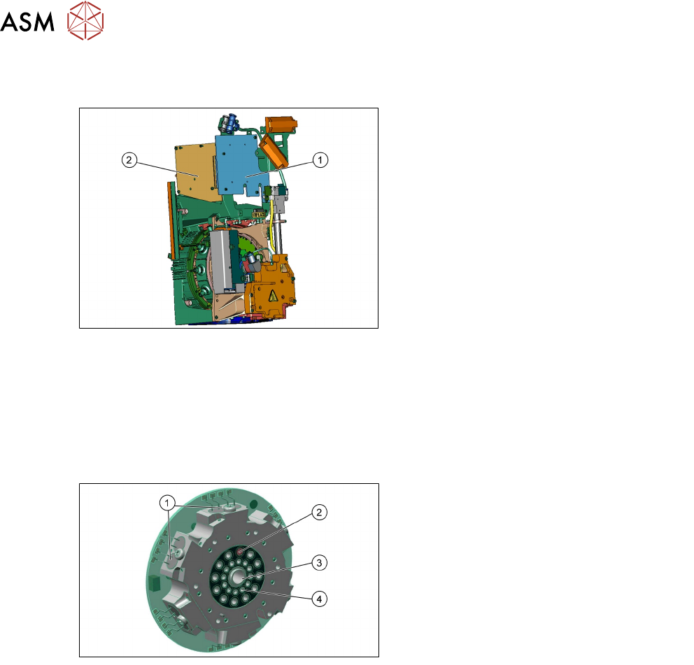
5.1.2.5 Intermediate Distributor
The intermediate distributor consists of two boards:
1. Intermediate distributor 1 is fitted to the
front of the head
2. Intermediate distributor 2 is fitted to the left
side of the head. For contactless energy
transmission an additional board is
plugged onto the intermediate distributor
●
LEDs show the operating voltages at the head and the state of the sensors.
●
Test connector for the track signals and test pins for analog signals.
●
Controlled power supply for incremental encoder from Z and star drive.
●
Interface for component sensor, vacuum unit, holding circuit vacuum sensor and EEPROM.
●
Startup control for the return cylinder.
5.1.2.6 Vacuum Valve Board
Valve Board details
1. Control valve for each segment
2. Vacuum or air kiss outer channels
3. Holding circuit input
4. The holding circuit measuring position
●
The valve board consists of twelve solenoid control valves (1), one for each segment.
●
The compressed air from holding circuit input (2) will be distributed into twelve segments.
●
In each channel there is a valve (1) which can open and close the compressed air of each
segment independently (3), after a placement the valve will switch OFF the compressed air for
this segment. Before pick up the valve will switch ON the compressed air and generate
vacuum.
●
Via the outer channels (4) we can measure the open and closed vacuum of the holding circuit.
●
In the 6 o`clock position the pick up and placement circuit is supplied with vacuum or air kiss
from the vacuum generator.
5 Placement Heads
5.1 CPP Head
Technical Training SIPLACE TX-Series 10/2016 57
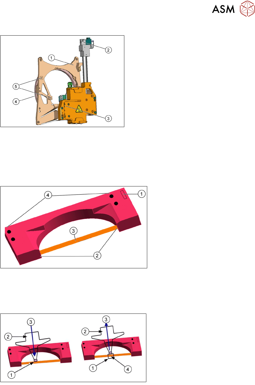
5.1.2.7 Front Plate
1. Front plate
2. Return cylinder
3. Z Axis with jaws and measuring system
Raceway
4. Fixture for pressure control valve
5. Fixture for pressure regulator valve
Front plate
●
The front plate of the CPP head is fixed to the head frame with four screws and needs to be
removed as a whole unit for service purposes.
●
With the exception of the PRV do not dismantle any other part from the front plate, as all parts
are specially aligned and cannot be adjusted in the field.
5.1.2.8 Component Sensor
1. Power/data supply connector
2. Transmitter and receiver unit
3. Laser beam
4. Fixture to head casing
(2x centering pins, 2x screws)
●
Each CPP Head is fitted with a component sensor in the pickup/place position.
●
This component sensor monitors the presence and/or component height after pickup and
before placement.
●
The sensor is fixed to the head with two screws and can be replaced as a complete unit
during service work.
1. Reading out the Z position, if the
laser beam is interrupted (top
diagram) or has been released
again (bottom diagram)
2. Nozzle
3. Downwards (top diagram) or
upwards (bottom diagram)
movement
4. Component
The component sensor signal is directly linked to the axis controller (measurement system) of the
Z Axis. This enables the reading of the Z position during upwards and downwards movement.