00198168-02_Technical_Training_TX-Series_EN.pdf - 第65页
5 Placement Heads 5.1 CPP Head Technical Training SIPLACE TX-Series 10/2016 65 Placement Procedure "High force": Placement force depends on current of Z Axis to determine end signal of Z Axis down and vacuum ge…
5 Placement Heads
5.1 CPP Head
64 Technical Training SIPLACE TX-Series 10/2016
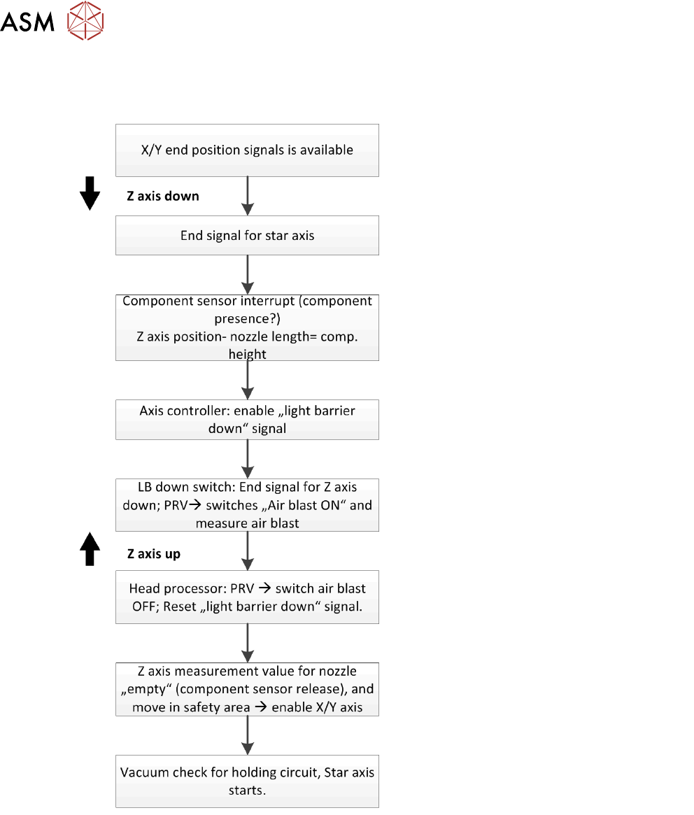
5.1.3.3 Standard Placement Workflow
Standard Placement
In this mode (light barrier down) the placement force at the CPP Head is around 2.6N.
During the production, a nozzle scanning run is performed after 350 head cycles (can be set by
SIPLACE service if required) and after the completion of the board currently processed.
The nozzle quality check can be configured in four different levels via the station interface: State
overview, Vakuum values, Hight values, Scan values.
Pick Up Procedure
With early vacuum move to pick up position the vacuum generator switches the vacuum on before
the Z Axis moves down.
"Contactless": The first component is picked up with standard mode to determine the Z Axis down
position, the picked component is rejected. The next components are picked up with the absolute
position of Z Axis down.
5 Placement Heads
5.1 CPP Head
Technical Training SIPLACE TX-Series 10/2016 65
Placement Procedure
"High force": Placement force depends on current of Z Axis to determine end signal of Z Axis down
and vacuum generator switch to air blast.
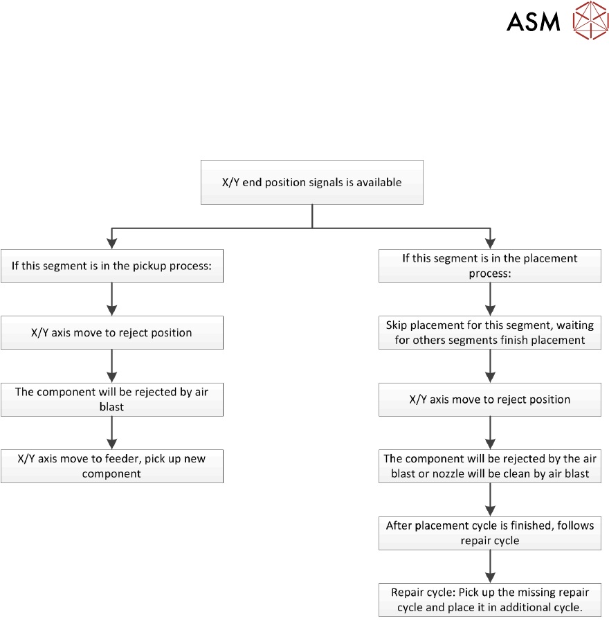
Reject Procedure
"Defective" or "missing" is determined by:
●
Optical centering
●
Component sensor
Temperature Compensation
The temperature sensor is regularly checked and offset value will be calculate and will be used to
increase placement accuracy.
5 Placement Heads
5.1 CPP Head
66 Technical Training SIPLACE TX-Series 10/2016
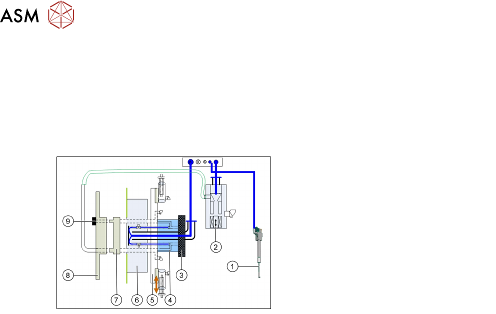
5.1.4 Vacuum System Overview
5.1.4.1 Vacuum System Function Overview
The Vacuum consists of two main parts:
●
Pickup/placement circuit: supply vacuum to pickup component from feeder or air kiss to place
it onto PCB.
●
Holding circuit: holding the component on the nozzle when component is on nozzle but not in
pickup position.
1. Retract Unit Z Axis
2. PRV
3. Silencer
4. Holding Circuit
5. Star frame with DP drives
6. Valve board
7. Distributor disk
8. Rear cover Head
9. Holding Circuit Sensor
●
The pneumatic distributor supplies the PRV (2), the holding circuit (4) and the retract unit (1)
with 4.5bar compressed air.
●
The compressed air is fed directly through the holding circuit (4) to the valve terminal (6).
There it is distributed into 12 channels, each channel has it own pneumatic valve, which can
open and close this channel.
●
The compressed air is fed from the valve terminal to the holding circuit (4). The vacuum for
the holding circuit of all 12 segments is generated there via 12 venturi nozzles.
●
The vacuum is fed from the holding circuit via the star frame (5) to the nozzle.