00198168-02_Technical_Training_TX-Series_EN.pdf - 第72页
5 Placement Heads 5.1 CPP Head 72 Technical Training SIPLACE TX-Series 10/2016 5.1.6 Board Description 5.1.6.1 Intermediate Distributor 1 and 2 Intermediate Distributor 1 1. LEDs 2. X2 Connector for flat ribbon cable to …
5 Placement Heads
5.1 CPP Head
Technical Training SIPLACE TX-Series 10/2016 71
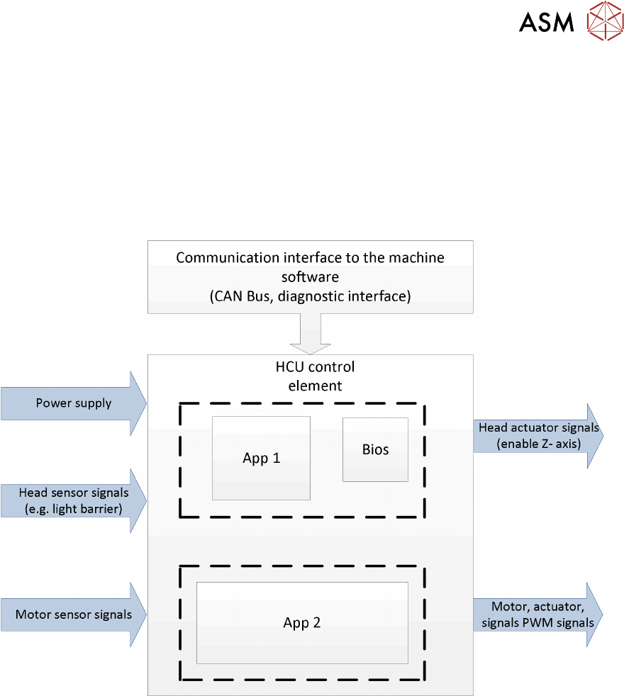
MHCU Function Power Supply
The power supply delivers 42V for the electronic and Z Axis.
The power cube on the head interface (C700) supplies the MHCU with 25V.
All required internal voltages (+24V, +15V, -15V, +5V, +3.3V, +1.5V) are generated by the head
interface at the gantry.
In addition, the operating voltages for the axes (150 V for Star / 42V for Z) are supplied by the
machine power supply.
MHCU Function
The head control unit is responsible for central control and adjustment of the axis and also for
communication with the station computer via CAN bus.
Tasks of the software application:
●
BIOS is responsible for the booting of the MHCU
●
Application 1: communication with machine software
●
Application 2: motor control
5 Placement Heads
5.1 CPP Head
72 Technical Training SIPLACE TX-Series 10/2016
5.1.6 Board Description
5.1.6.1 Intermediate Distributor 1 and 2
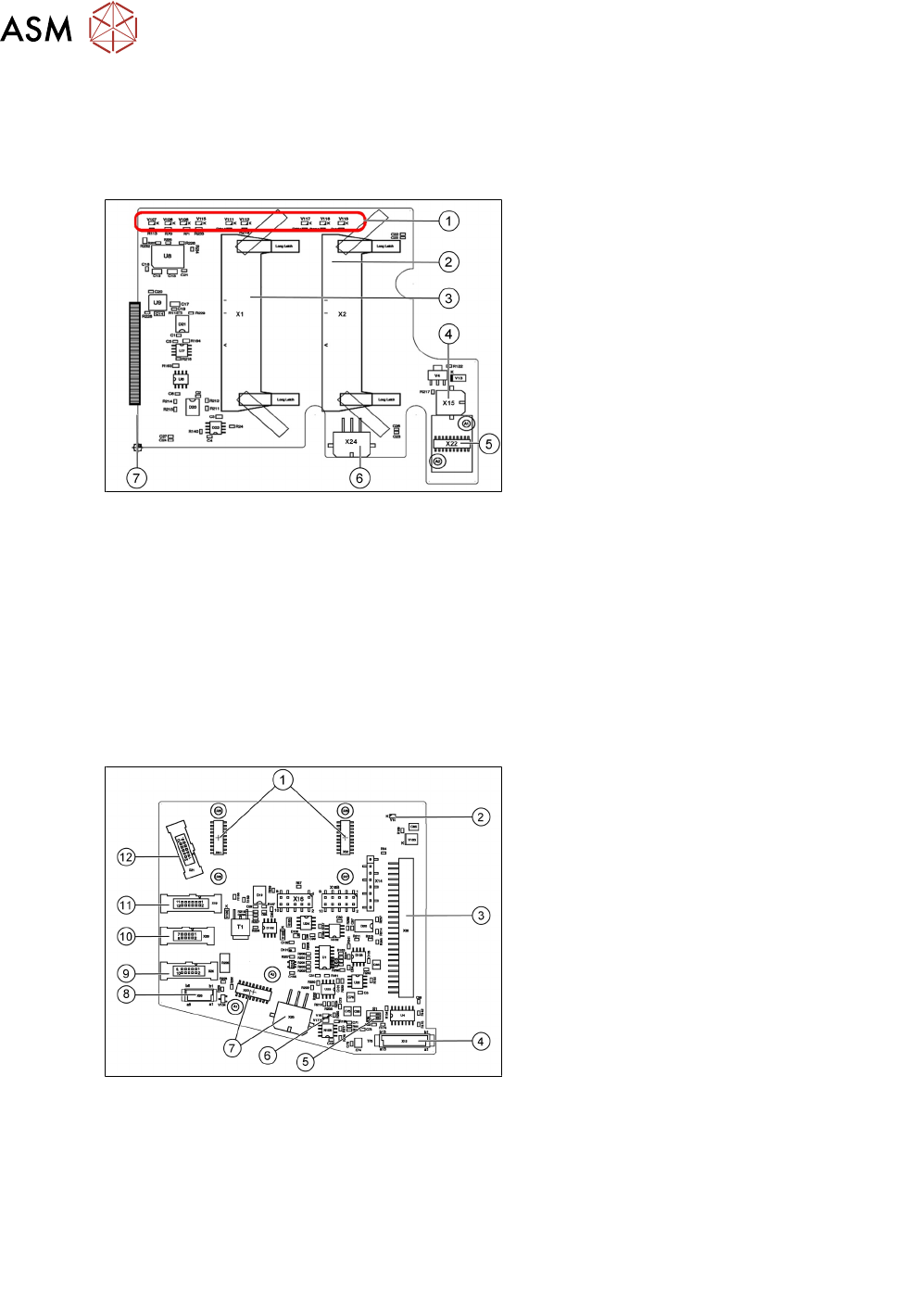
Intermediate Distributor 1
1. LEDs
2. X2 Connector for flat ribbon cable to the
head adapter
3. X1 Connector for flat ribbon cable to the
head adapter
4. X15 Retract cylinder
5. X22 Connector Z Axis encoder
6. X24 Z Motor
7. X25 Connector intermediate distributor 2
LEDs
V106 Operating voltage +15 V V115 Operating voltage +24
V_DP/3.3V_DP
V107 Operating voltage + 5 V V116 Status of pressure control valve
V108 Operating voltage -15 V V117 Z-down sensor "ON"
V111 Z Axis encoder error V118 Return cylinder moved out
V112 Star Axis encoder error
Intermediate Distributor 2
X14, X16, X16B: Test connector CAN Bus
X27, X28: Test connector for FPGA
Either X20, X26 or X29 is used!
1. X31,X32 connector for the KE transducer
control board (CPP Head from version 05)
2. 24V DP switched
3. X30 connector to intermediate
distributor 1
4. X12 digital pressure control valve
5. Switch S1.1: CAN test
Switch S1.2: CAN ID Set both switches to
OFF
6. V17/V18 potential display, voltage present
7. X23 star encoder connectors (track
signals) with EEPROM, X25 star
motor
8. X20 not used
9. X26 energy transmission (contactless)
CPP Head from version 05
10. X29 energy transmission, slip ring (24
V) (CPP Head < version 05)
11. X19 vacuum sensor holding circuit
12. X21 CO sensor
5 Placement Heads
5.1 CPP Head
Technical Training SIPLACE TX-Series 10/2016 73
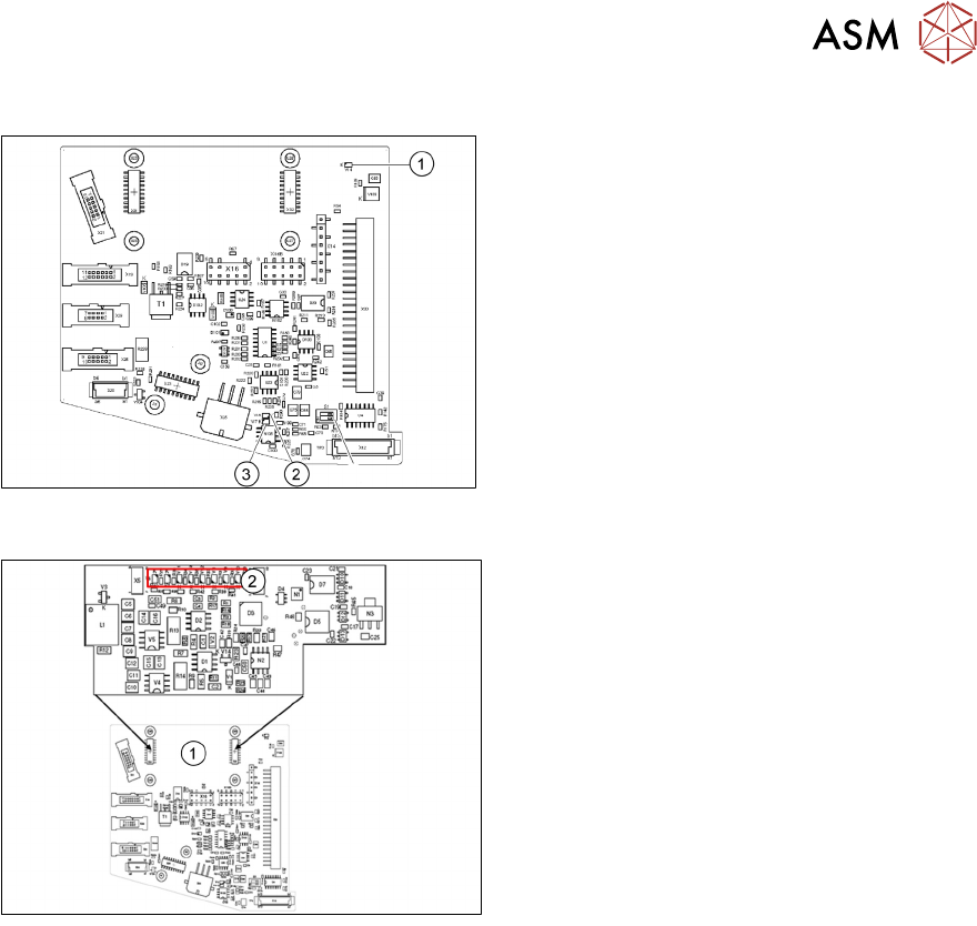
LEDs
1. V14 +24VDC_DP_switched
2. V18 Potential display:
LED on = voltage present
3. V17 Potential display:
LED on = voltage present
5.1.6.2 Addressing the Contactless Energy Transformer
For contactless energy transmission an
additional board is plugged onto the
intermediate distributor 2
1. X31/X32
2. LEDs
V6 Maximum current exceeded
V7 Continuous current too high
V9 KE control switched on (normal opera-
tion ON)
V10 KE transducer error switched OFF
5.1.7 Calibration
5.1.7.1 Calibration Overview
Calibration - Overview Description
●
Measuring component camera: This determines the relationship of "camera pixel size to
resolution of machine measuring system (X,Y)", "camera center point in X and Y direction"
and the "torsion angle of the CCD sensor".
●
Head offset: the head offset is the distance between the PCB camera and the nozzle
(segment 1). The target is a fixed value, to which an offset value (from the head calibration) is
added.
TX micron only: During the placement cycle the head offset is periodically checked and
calibrated.
●
Segment offset top: the top segment offset involves turning the calibration tool in the
component camera in 0°, 90°, 180° and 270° steps. The value determined is that of the
rotating center of the nozzle tip in relation to the component camera center in the X and Y
direction.
●
Segment offset bottom: the bottom segment offset involves recording and measuring the
calibration tool in the 0°, 90°, 180° and 270° positions. The value determined is that of the
rotating center point of the nozzle tip when the Z Axis is extended in relation to the PCB
camera. Segment 1 forms the reference (X=0, Y=0) to the other segments.