00198168-02_Technical_Training_TX-Series_EN.pdf - 第92页
5 Placement Heads 5.2 C&P20 P/M2 Head 92 Technical Training SIPLACE TX-Series 10/2016 5.2.2 Main Parts/ Unit Overview 5.2.2.1 Z Axis Drive 1. Mounting for Z Axis 2. Incremental measurement system 3. Primary part of l…

5 Placement Heads
5.2 C&P20 P/M2 Head
Technical Training SIPLACE TX-Series 10/2016 91
5.2.1.2 Technical Data*
Description C&P20 P
Component range 01005 to 2220, Melf, SOT,SOD: Camera type
23
0201 (metric) to 2220, Melf, SOT, SOD,
Bare-Die, Flip-Chip Camera type 41
Component height max 4.0 mm
Component weight max 1.0 g
Placement accuracy ± 30μm / 3σ Camera type 23
± 25 μm / 3σ Camera type 41
Angle accuracy ± 0.5° at 3σ
Programmable Placement force 1.3 - 4.5 N
Nozzle types 4xxx, (4235 calibration nozzle)
Nozzle changer NC Base structure CPx / Short
C&P20 M2 Head – Technical Data*
Description C&P20 M2
Component range 0201 (metric) to 2220, Melf, SOT, SOD,
Bare-Die, Flip-Chip Camera type 41
Component height max 4.0mm
Component weight max 1.0g
Placement accuracy with "high precision flag" ± 15μm / 3σ**
± 20μm / 3σ
Placement accuracy without "high precision
flag"
± 25μm / 3σ
Angle accuracy ± 0.3° / 3σ***
± 0.2° / 3σ****
Programmable Placement force 1.5 - 4.5 N
Nozzle types 4xxx, (4257 calibration nozzle)
Nozzle changer NC Base structure CPx / Short
* For full specification refer to the user manual.
**Only with SIPLACE TX2i micron 15μm accuracy class
***For SIPLACE TX micron with accuracy class 25μm
****For SIPLACE TX micron with accuracy class 20μm or SIPLACE TX2i micron 15μm
Machine Types
Machines X-Series S SX1 V2 SX2 V2 TX Series TX micron
C&P20 P X X X
C&P20 M2 X
Preconditions/ Requirement
●
TX Series: Station software ≥ SW709; SIPLACE Pro. ≥ 13
●
TX micron: Station software ≥ SW710.0; SIPLACE Pro. ≥ 14
Configuration
●
Vacuum pump operation (Standard).
●
Venturi System (Compressed air/ vacuum) operation (Option).
●
Component cameras:
– SST 23 (01005-2220 max. 6x6 mm/Visual field: 8.4 x 8.4 mm/Resolution: 17.1 µm/pixels)
– SST 41 (03015-2220 max. 6x6 mm/Visual field: 8.9 x 8.9 mm/Resolution: 10.1 µm/pixels)
●
Nozzle types 4xxx with corresponding magazines.
5 Placement Heads
5.2 C&P20 P/M2 Head
92 Technical Training SIPLACE TX-Series 10/2016
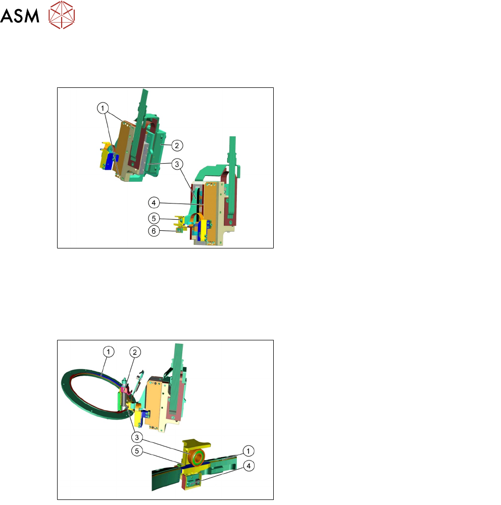
5.2.2 Main Parts/ Unit Overview
5.2.2.1 Z Axis Drive
1. Mounting for Z Axis
2. Incremental measurement system
3. Primary part of linear motor
4. Secondary part of linear motor
5. Ceramic jaw
6. Light barrier Z-down (analog)
●
The Z Axis is supplied with 40V/ 3,28A from the MHCU.
●
The incremental reader head has an EEprom on the connector to store statistic and axis data.
●
The Z Axis unit and the raceway are complementary parts, it is not possible to change one of
the above mentioned parts.
5.2.2.2 Z Axis
1. Raceway
2. Segment 1
3. DP ball bearing
4. Light barrier Z-down
●
The Z-drive is not a spare part!
●
The light barrier Z-down is not a spare
part!
5. Jaw
Functionality of the Z-drive
●
The ceramic jaw is mounted to the primary part of the Z Motor for mechanical docking of the
DP drives.
●
The analog Z-down sensor is located at the placement position for recognition of the Z Axis
set down position.
●
When the Z Axis springs into place, this sensor sends a signal to the axis controller card
(MHCU) The "light barrier down" signal is directly linked to the measurement signal of the
Z Axis incremental encoder.
5 Placement Heads
5.2 C&P20 P/M2 Head
Technical Training SIPLACE TX-Series 10/2016 93
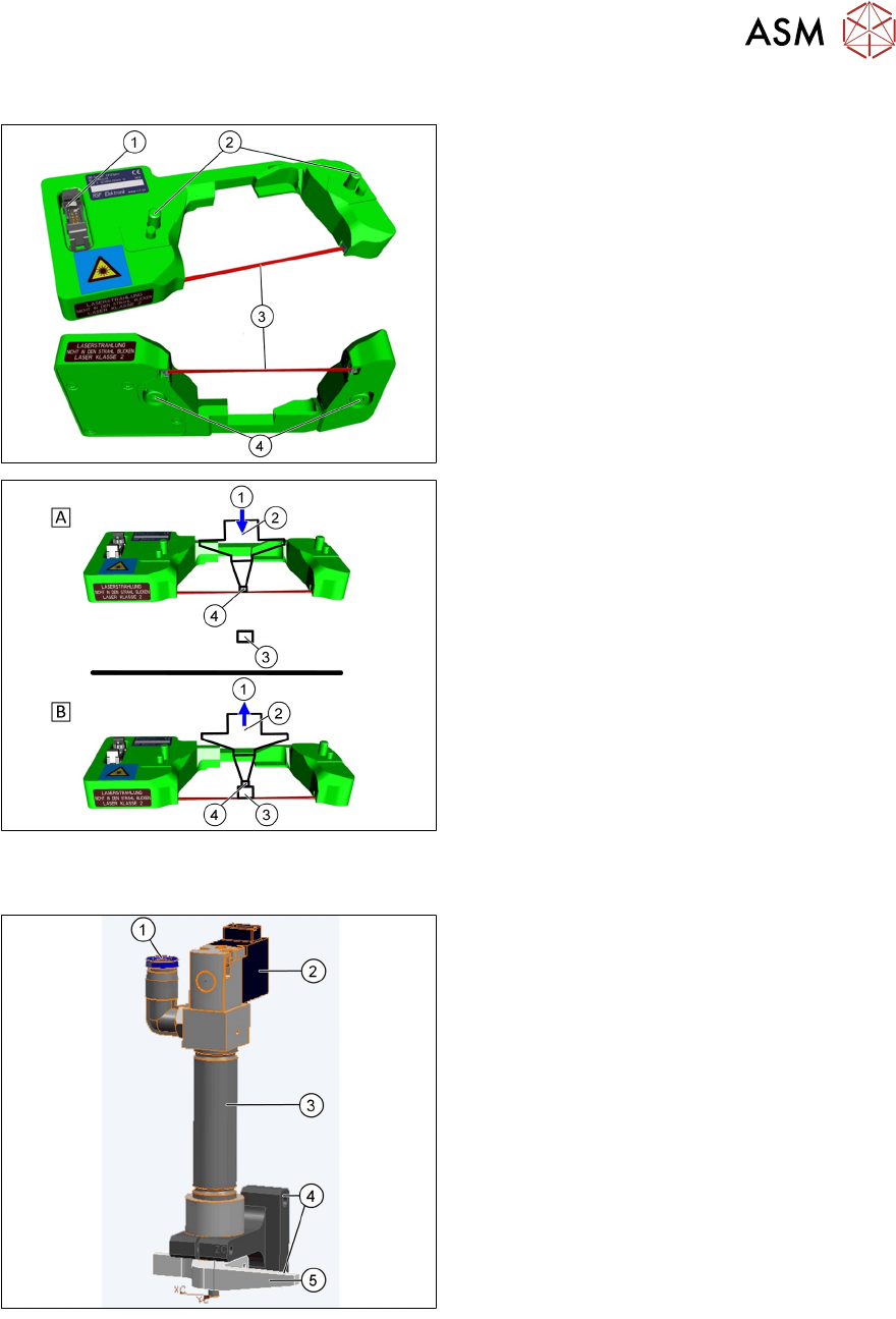
5.2.2.3 Component Sensor
1. Power/ data supply cable
2. Mounting to housing
3. Laser beam
4. Transmitter and receiver unit with
protected prisms
●
The component sensor is installed in the
pickup-placement position on the C&P20 P
Head.
●
The sensor is fixed to the head with two
screws (2).
1. Downwards (A) or upwards (B) movement
2. Nozzle
3. Component
4. Reading out the Z position, if the laser
beam is interrupted (A) or has been
released again (B)
Component Sensor Functions
●
The component sensor determines the
component and nozzle height during the
placement process.
●
The component sensor signal is directly
linked to the measurement signal of the Z
Axis incremental encoder for recording the
position.
5.2.2.4 Retract Unit
1. Compressed air connection
2. Solenoid valve
3. Pneumatic cylinder
4. Mounting of retract unit
5. Actuator to move the Z Axis
Retract unit Functions
●
The retract unit is installed on the Z Axis
and is responsible for protecting the Z Axis
from damage by moving it into a safe
position in the case of unexpected events
e.g. power cuts or machine shutdown.
●
The retract unit is fixed with two screws
and can be easily replaced during service
work.