00193891-0702_AI_LP_Barcode_DE+EN.pdf - 第138页
1 Montageanleitung LP-Barcode-Leser SIPLACE 1.12 Tips & Tricks zum Barcode-Leser Ausgabe 10/2009 138 Hierzu in das jeweilige Fenster k licken, worauf sich eines der un ten abgebildeten Fenster öffnet. Über die T ast …
SIPLACE 1 Montageanleitung LP-Barcode-Leser
Ausgabe 10/2009 1.12 Tips & Tricks zum Barcode-Leser
137
1
1
1
1 Montageanleitung LP-Barcode-Leser SIPLACE
1.12 Tips & Tricks zum Barcode-Leser Ausgabe 10/2009
138
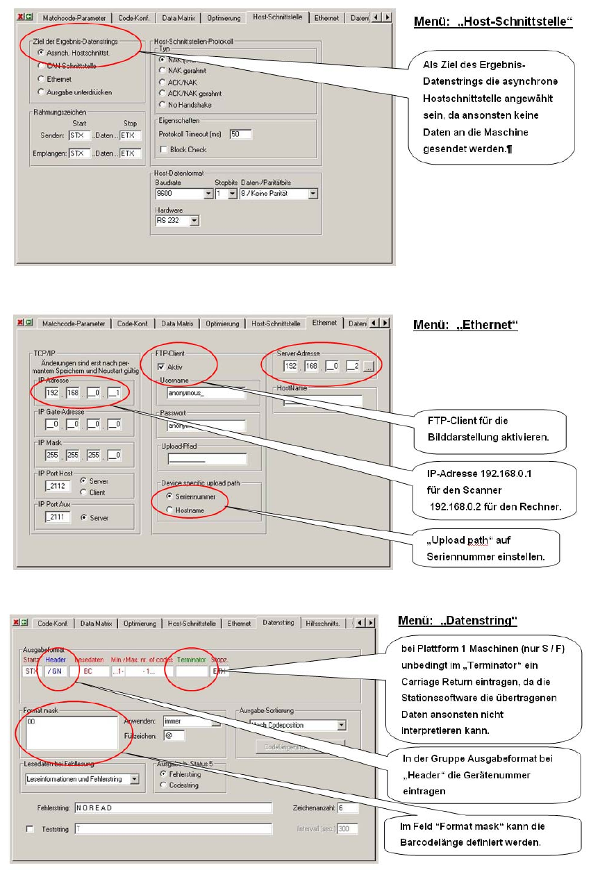
Hierzu in das jeweilige Fenster klicken, worauf sich eines der unten abgebildeten Fenster öffnet.
Über die Tastatur wird dann in der oberen Zeile ein “/“ eingegeben und anschließend mit der Maus
im Auswahlfenster entweder “GN“ für den Header oder “CR“ für den Terminator ausgewählt. 1
1
1
1
1
1

SIPLACE 2 PCB barcode scanner assembly instructions
10/2009 Edition 2.1 Overview
139
2 PCB barcode scanner assembly
instructions
2.1 Overview
These instructions describe how to assemble the
"PCB barcode scanner for 1D" (item no. 00119682-xx) and
"PCB barcode scanner for 2D" (item no. 00119679-xx) (SIPLACE HS/HF)
"PCB barcode scanner for 2D" (item no. 00119689-xx) (SIPLACE S/F)
options on the single or dual conveyor. 2
The placement machine may remain on the line while the PCB barcode option is installed. 2
2.2 Use and arrangement
With the PCB barcode scanner, the barcode may be scanned (recorded and decoded) on the top
or bottom of a PCB. The scanning result is forwarded via a serial port to the machine controller for
further processing. 2
It may be used on a single or dual conveyor. The "PCB b
arcode topside/underside..." retrofit kit
contains the parts for the barcode scanner on the single conveyor. For the dual conveyor or bar-
code topside and underside, you will need
the relevant number of "PCB barcode optional...." ret-
rofit kits. 2
During the retrofit, the scanning head(s) are fitte
d onto profiled rails, which are installed above and
below the PCB input belt.
One or two scanning heads are fixed to and can be a
djusted on a profiled rail, thus allowing them
to be aligned with respect to the barcode labels to be scanned. Barcode strips may be scanned
along or across the PCB travel direction. The scanning head and mount are aligned correctly and
then attached to the profiled rail (1D barcode scanner only). 2
The change from "barcode topside" to "barcode underside" is made either by moving the scanning
h
ead to the top or bottom profiled rail as required, or by fitting one scanning head for "barcode
topside" and one for "barcode underside" on conveyor 1 / 2.
The scanning heads are connected to the power supply at the d
istribution board (from the retrofit
kit). 2
2