00193891-0702_AI_LP_Barcode_DE+EN.pdf - 第152页
2 PCB barcode scanner assembly instructions SIPLACE 2.7 Installing the PCB barcode scanner 10/2009 Edition 152 : T o do this, loosen the following screws: Detach grounding term inal Loosen and remove screw Loosen and rem…
SIPLACE 2 PCB barcode scanner assembly instructions
10/2009 Edition 2.7 Installing the PCB barcode scanner
151
2.7 Installing the PCB barcode scanner
2.7.1 SIPLACE HF series / X-series / D3
: Switch the machine off at the main switch.
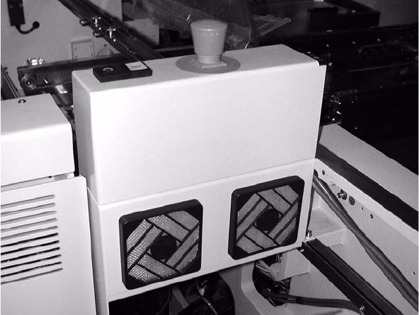
: Open the protective covers.
: Open the plexiglas cover over the input belt.
2
CAUTION: Dual conveyor only: 2
A side section of the input belt (exte
nsion kit) must be removed in order to install the fixing rail for
the barcode scanner. 2
2
2
2
2
2
2
2
2
2
2 PCB barcode scanner assembly instructions SIPLACE
2.7 Installing the PCB barcode scanner 10/2009 Edition
152
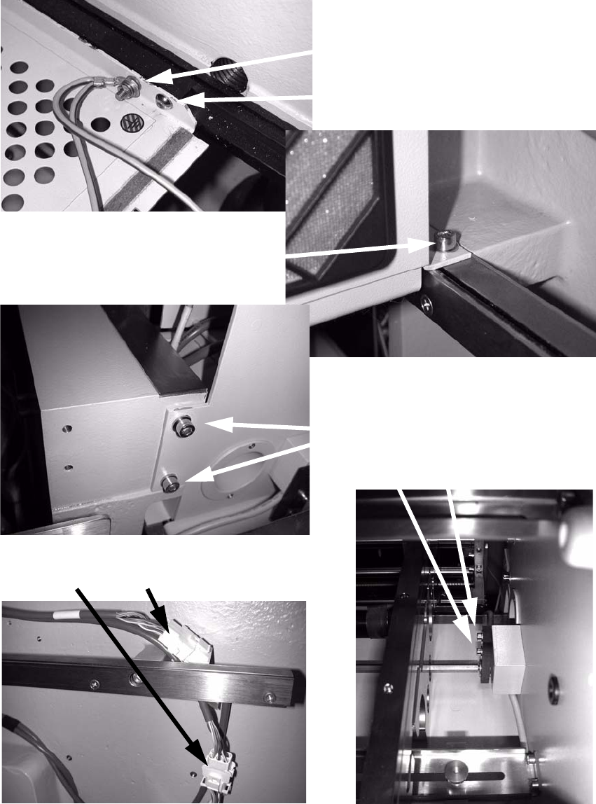
: To do this, loosen the following screws:
Detach grounding terminal
Loosen and remove screw
Loosen and remove screw
Loosen screws
Detach connections
2
: Remove the side section of the input belt (extension kit).
SIPLACE 2 PCB barcode scanner assembly instructions
10/2009 Edition 2.7 Installing the PCB barcode scanner
153
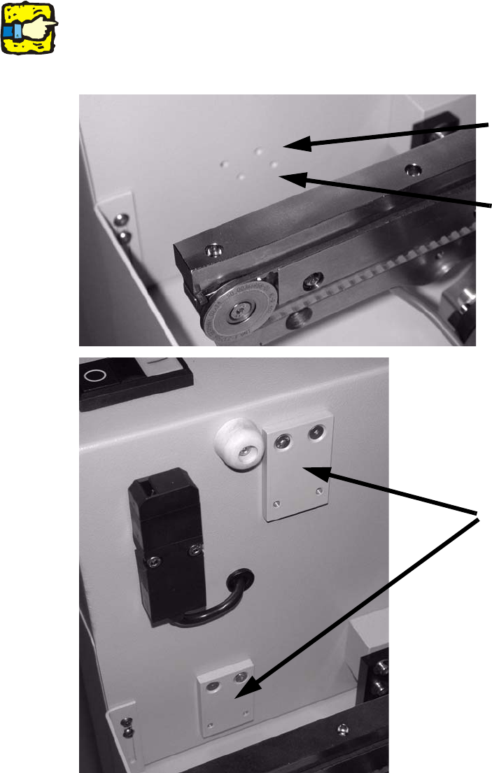
: Screw the adapter plate above (PCB barcode scanner topside) or below the input belt (PCB
barcode scanner underside) using 2 hexagon socket head screws on the left and right.
Screw on the adapter plates through the top holes.
2
If the screws are hard to tighten, tighten them first without the rail and then loosen them again.
This will break the paint in the screw holes. 2
Top holes for rail under-
neath with 2D scanner
Adapter plates
Bottom holes for rail on top
with 2D scanner
2
2
2