00193891-0702_AI_LP_Barcode_DE+EN.pdf - 第159页
SIPLACE 2 PCB barcode scanner assembly instructions 10/2009 Edition 2.7 Installing the PCB barcode scanner 159 Att ach the warning labels 2 : Attach the laser wa rning label to the Makrolon window on the input belt. Th e…
2 PCB barcode scanner assembly instructions SIPLACE
2.7 Installing the PCB barcode scanner 10/2009 Edition
158
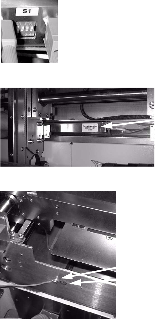
: Set the relevant switch for the connected scanner to OFF and the others to ON.
2
: Attach the barcode distributor using Velcro tape.
Barcode distributor
2
: Connect the protective earth to the side of the conveyor trough and attach the grounding point.
Protective earth connection
Grounding point
2
: Close all protective covers and protective hoods.
SIPLACE 2 PCB barcode scanner assembly instructions
10/2009 Edition 2.7 Installing the PCB barcode scanner
159
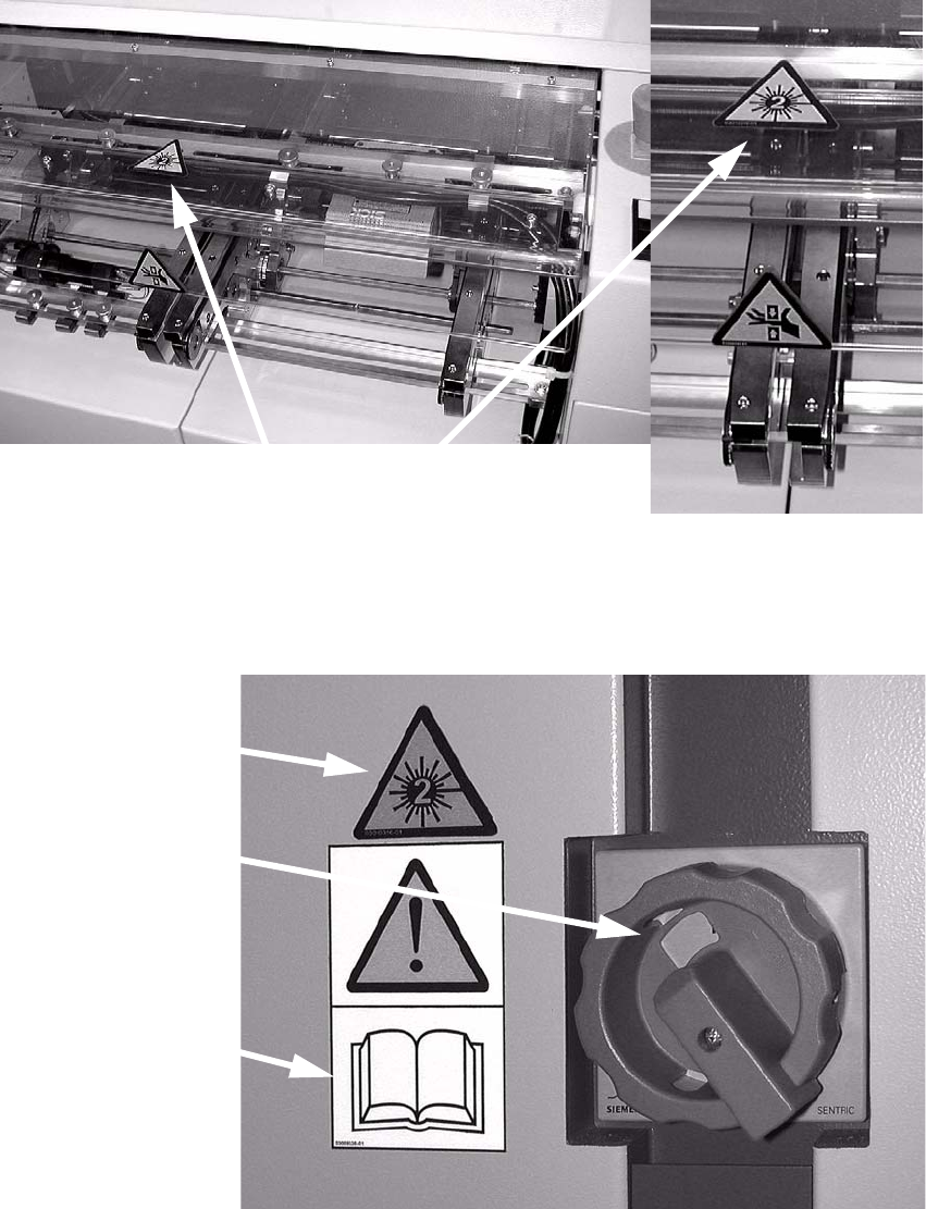
Attach the warning labels 2
: Attach the laser warning label to the Makrolon window on the input belt.
Th
e label is needed because a laser class 2 sensor
beam that is directed upwards while the
machine is in use could be directed outside.
Position of the label
2
: Stick the warning label W216 (item no. 03010316-xx) onto the cover, beside the main switch
and above the warning label concerning following the safety instructions in the operating in-
structions.
Main power switch
Warning label W216
Warning label
for safety
instructions
2

2 PCB barcode scanner assembly instructions SIPLACE
2.7 Installing the PCB barcode scanner 10/2009 Edition
160
: Set the distances between the 1D barcode scanner and the PCB so that the barcodes are read
reliably. This is achieved by moving the cross-rails up or down in the slots (see scanning field
diagram in
Chapter 2.11.4).
: Fo
r the 2D barcode scanner, set the distance to exactly 60 ± 1 mm.
Use the adjusting gauge provided
(see photograph on page 177).
The 2D scanner only works in this focus range.
2
The SICK software (version > 4.1) can be used to check the setting. 2
2
: Switch the placement machine on at the main switch.