00193891-0702_AI_LP_Barcode_DE+EN.pdf - 第163页
SIPLACE 2 PCB barcode scanner assembly instructions 10/2009 Edition 2.7 Installing the PCB barcode scanner 163 : Drill 4 holes through the gauge and into the extension kit. Slots for fixing the drilling gauge Drill these…
2 PCB barcode scanner assembly instructions SIPLACE
2.7 Installing the PCB barcode scanner 10/2009 Edition
162
2.7.3 Creating the fixing holes
Tools required 2
– Screw clamp 120 mm
– Power drill or cordless screwdriver
– Drill bit (3.3 mm)
–M4 tap
– ratchet tapper
– 2x M4x12 screw / HS-50
– Drilling gauge (item no.: 03026214-01) / HS-50.
2
2
Before starting to drill, cover all the electrical components in the extension kit in order to protect
them against drilling dust. 2
2
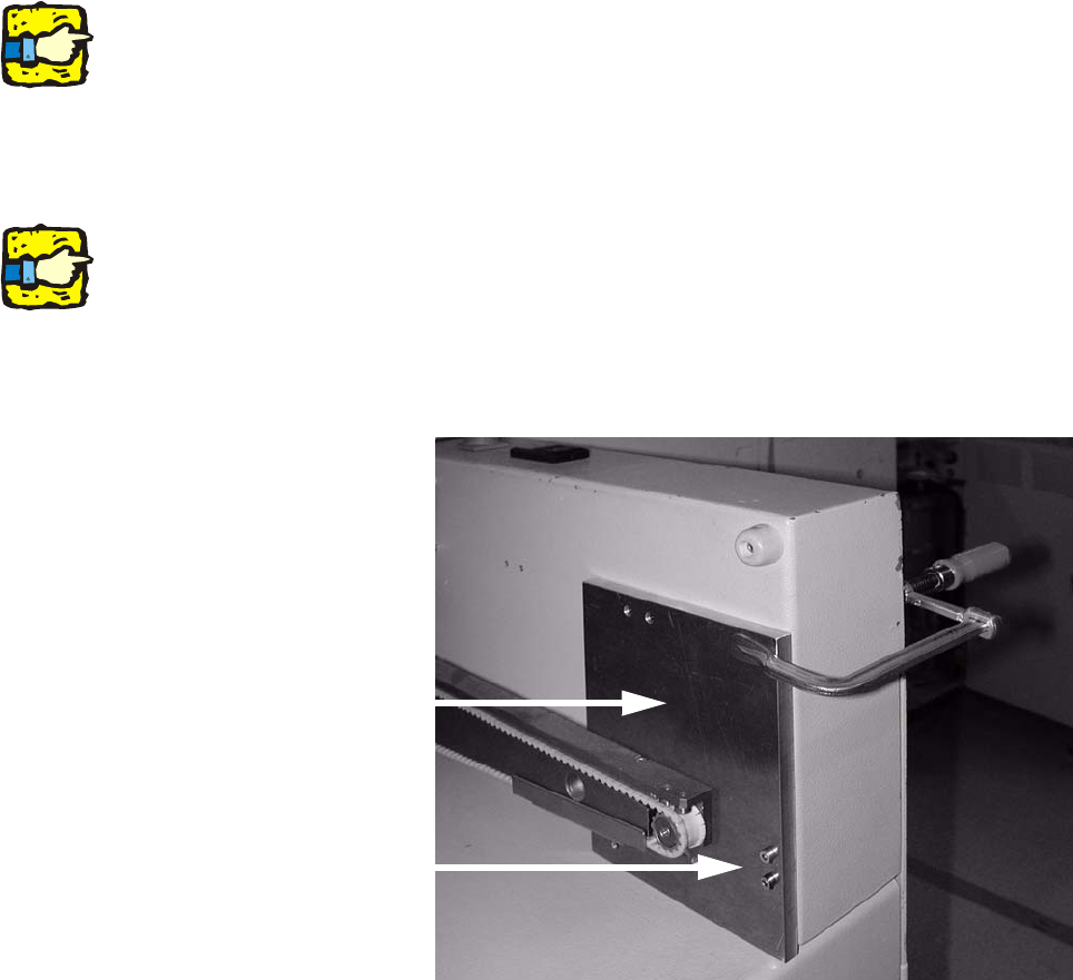
: Remove the hand guard on the extension kit.
: Fit the drilling gauge to the two threads for the hand
guard.
2
Make sure that the drilling gauge is seated on the base of the extension kit. 2
2
2
: Use the screw clamp to further secure the drilling gauge.
Drilling gauge
Fix drilling gauge using
these two screws.
2
SIPLACE 2 PCB barcode scanner assembly instructions
10/2009 Edition 2.7 Installing the PCB barcode scanner
163
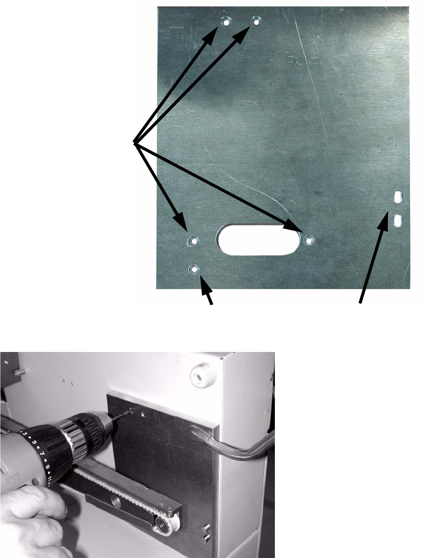
: Drill 4 holes through the gauge and into the extension kit.
Slots for fixing the drilling
gauge
Drill these four holes
This hole only has to be drilled for
the old PCB barcode unit.
2
: Drill the holes on both sides of the extension kit.
: Remove the drilling gauge.
2 PCB barcode scanner assembly instructions SIPLACE
2.7 Installing the PCB barcode scanner 10/2009 Edition
164
: Tap the thread in the holes using the ratchet tapper and M4 tap.
: Clean the mach
ine to remove all drilling dust.
2.7.3.1 Mechanical installation
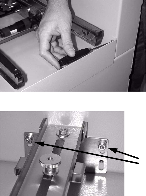
: Open the protective cover over the PCB input belt.
: If necessary, remove the hand guard on the end face (2 hexagon socket head screws on each
side).
T
his is not absolutely necessary, but it does make it easier to a
ccess the working area.
2
: Fit the bottom cross-rail using the two top holes (M 4x8).
Screws
2
2
2
2