00193891-0702_AI_LP_Barcode_DE+EN.pdf - 第176页
2 PCB barcode scanner assembly instructions SIPLACE 2.7 Installing the PCB barcode scanner 10/2009 Edition 176 : Fix the cables using cabl e ties. 2 : Open the pane l on the left -hand side of the inp ut extension kit. :…
SIPLACE 2 PCB barcode scanner assembly instructions
10/2009 Edition 2.7 Installing the PCB barcode scanner
175
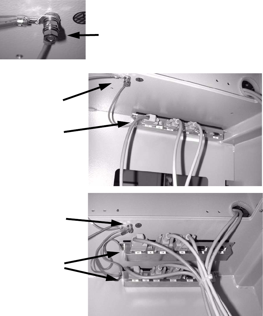
: Stick the distributor rail (SC) or both distributor rails (DC) inside the drawer unit (see photo-
graph below).
: Connect the grounding cable for the distributor rail to the available grounding point.
Th
e grounding cable must be connected with plai
n washer, snap ring and nut M5.
Grounding
Distributor rails
HS-50 single conveyor
Grounding
Distributor rail
HS-50 dual conveyor
Grounding
2
2
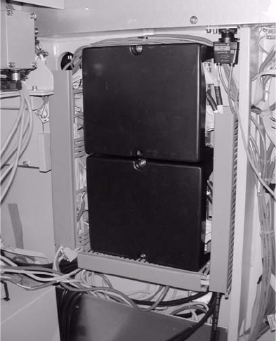
: Fit the cover to the conveyor control.
2 PCB barcode scanner assembly instructions SIPLACE
2.7 Installing the PCB barcode scanner 10/2009 Edition
176
: Fix the cables using cable ties.
2
: Open the panel on the left-hand side of the input extension kit.
: Remove the cover from the conveyor control and connect the cable to X 23 and X24.
2
Fig. 2.7 - 5 HS-50 conveyor controller
2
The jumper assignment for the interface (SIPLACE / SMEMA) on the conveyor control must cor-
respond to the current interfaces otherwise the barc
ode data will not be forwarded correctly to the
station software. 2
J1 = SIPLACE/SMEMA upstr
eam station
J2 = SIPLACE/SMEMA downstream station
SIPLACE = setting 1-2; SMEMA setting 2-3. 2
2
2
2
2
2
2
2

SIPLACE 2 PCB barcode scanner assembly instructions
10/2009 Edition 2.7 Installing the PCB barcode scanner
177
Attaching the warning label 2
: Attach the three laser warning labels to the Makrolon window on the input belt.
Th
e labels are needed because a laser class 2 sensor
beam that is directed upwards while the
machine is in use could be directed outside.
2
: Tighten any screws that are still loose.
: Refit and close all removed panels, covers and protective hoods.
: Set the distances between the 1D barcode scanner an
d the PCB so that the barcodes are read
reliably. This is achieved by moving the cross-rails up or down in the slots (see scanning field
diagram in
Chapter 2.11.4).
: For the 2D barcode scanner, set the dist
ance to exactly 60 mm +/- 1 mm.
Use the adjusting gauge provided.
The 2D scanner only works in this focus range.
Distance from 2D barcode scanner
to PCB: 60 mm +/- 1 mm.
The SICK software (version > 4.1)
can be used to check the setting.2
Setting gauge
2