00193891-0702_AI_LP_Barcode_DE+EN.pdf - 第183页
SIPLACE 2 PCB barcode scanner assembly instructions 10/2009 Edition 2.7 Installing the PCB barcode scanner 183 : Remove the rubber mounting . 2 2 : Loosen the three screws on the lef t side of the extension kit. 3 screws…
2 PCB barcode scanner assembly instructions SIPLACE
2.7 Installing the PCB barcode scanner 10/2009 Edition
182
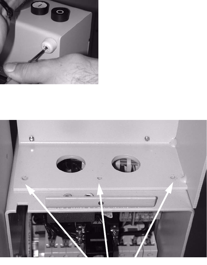
: Using the drill or cordless screwdriver, drill a 10 mm diameter hole (see diagram above for po-
sition).
: Cut out the slot with a compass saw or hacksaw.
: Deburr sharp edges.
: Refit the top of the extension kit.
2
2.7.6 Mechanical and electrical installation
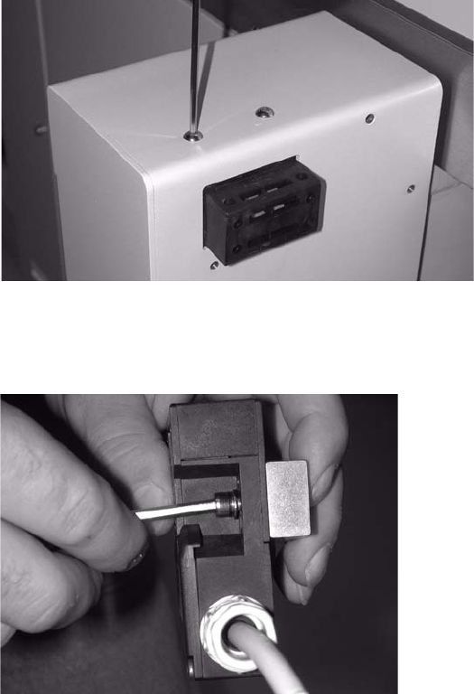
: Unscrew the cover switch.
The screws are secured with locking adhesive.
2
2
: Remove the spacer block from the cover switch.
2
2
2
SIPLACE 2 PCB barcode scanner assembly instructions
10/2009 Edition 2.7 Installing the PCB barcode scanner
183
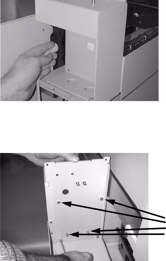
: Remove the rubber mounting.
2
2
: Loosen the three screws on the left side of the extension kit.
3 screws
2
2
2
2
2
2
2 PCB barcode scanner assembly instructions SIPLACE
2.7 Installing the PCB barcode scanner 10/2009 Edition
184
: Pull the extension kit gently outwards and thread the cover switch cable through between the
machine and the extension kit (see photo).
2
2
: Place the lower transverse rail in the extension kit.
: Screw the three screws up again.
: Screw the new s
idewalls into the PCB feeder with four screws (5 x 8).
4 screws
2
2
: Screw the cover switch on loosely.
The screw belongs in the through hole, not the slot.